


Net Oil Computer Supplement 7
NOC Overview
NOC Overview NOC ConfigurationUsing the DisplayBefore You Begin
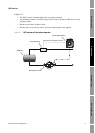
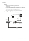
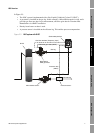
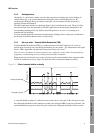
In Figure 2-3:
• The NOC system is implemented with a Gas-Liquid Cylindrical Cyclone™ (GLCC).
• A gas meter is installed on the gas leg. In this example, a Micro Motion meter is used, and it
provides gas flow rate data for gas measurement, and drive gain data for Transient Mist
Remediation via a HART connection.
• Density-based water cut data is used.
• A pressure sensor is installed on the oil/water leg. This enables pressure compensation.
Figure 2-3 NOC system with GLCC
P
GLCC
Micro Motion sensor
Gas leg
Oil/water leg
Micro Motion
TMR gas meter
Pressure sensor
Series 3000 platform
Pressure data
(HART)
Gas flow rate data (Frequency input)
TMR drive gain data (HART)