


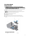

Installing The External Cooling Fan
CAUTION: Many repairs may only be done by a certified service technician. You should only perform
troubleshooting and simple repairs as authorized in your product documentation, or as directed by the online or
telephone service and support team. Damage due to servicing that is not authorized by Dell is not covered by your
warranty. Read and follow the safety instructions that came with the product.
CAUTION: Do not operate the system with the cover removed for a duration exceeding 5 minutes.
1. Turn off the system, including any attached peripherals, and disconnect the system from the electrical outlet and
peripherals.
2. If applicable, rotate the system feet inward and lay the system on its side on a flat, stable surface.
NOTE: For systems installed with the wheel assembly, ensure that you lay the system on a sturdy, stable
surface with the wheel assembly extending off the edge of the surface.
3. Open the system.
4. Remove the cooling shroud.
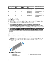
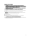
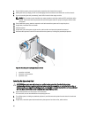
5. Route the external cooling fan power cable into the system through the slot at the back of the chassis.
6. Align and insert the two lower hooks on the external cooling fan into the corresponding slots on the back of the
chassis.
7. Rotate the top of the external cooling fan toward the chassis till the upper hook locks into place.
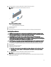
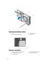
8. Use the four screws to secure the external cooling fan to the chassis.
9. Secure the external cooling fan power cable using the clips inside the chassis.
10. Connect the external cooling fan power cable to the FAN2 connector on the system board.
11. Install the cooling shroud.
12. Close the system.
13. If applicable, place the system upright on a flat, stable surface and rotate the system feet outward.
14. Reconnect the system to its electrical outlet and turn the system on, including any attached peripherals.
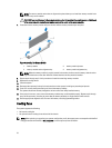
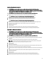
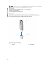
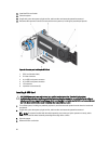
Internal USB Memory Key (Optional)
An optional USB memory key installed inside your system can be used as a boot device, security key, or mass storage
device. The USB connector must be enabled by the Internal USB Port option in the Integrated Devices screen of the
System Setup.
To boot from the USB memory key, configure the USB memory key with a boot image and then specify the USB memory
key in the boot sequence in the System Setup.
NOTE: To locate the internal USB connector (INT USB) on the system board, see System Board Connectors.
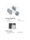
Replacing The Internal USB Key
CAUTION: Many repairs may only be done by a certified service technician. You should only perform
troubleshooting and simple repairs as authorized in your product documentation, or as directed by the online or
telephone service and support team. Damage due to servicing that is not authorized by Dell is not covered by your
warranty. Read and follow the safety instructions that came with the product.
1. Turn off the system, including any attached peripherals, and disconnect the system from the electrical outlet and
peripherals.
2. If applicable, rotate the system feet inward and lay the system on its side on a flat, stable surface.
83