


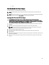
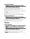
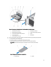
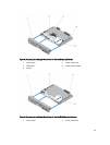
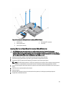
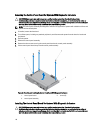

Figure 60. Removing and Installing the Control-Panel Assembly in a Rack-Mode System
1. LCD module ZIF connector 2. VGA module connector
3. VGA module cable connector 4. control-panel assembly connector
5. control-panel assembly cable connector 6. screw
7. control-panel board 8. VGA module
9. control panel for rack mode
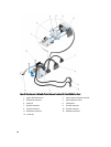
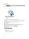
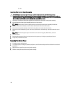
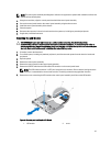
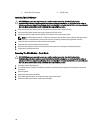
7. If you are replacing the control-panel assembly, remove the information tag by following the steps below:
a. Locate the tabs on the information tag.
b. Use a flat screwdriver to press the tabs on the tag one at a time.
c. Pull the information tag out of the slot to remove it from the control-panel assembly.
NOTE: Retain the information tag for replacement in the new control-panel assembly.
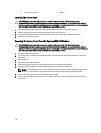
Figure 61. Removing and Installing the Information Tag
1.
information tag 2. tabs (2)
111