


4. Offset the front wheel assembly unit slightly to the back of the system to release the retention hooks, and pull out
the front wheel assembly unit.
5. Remove the screw securing the back wheel assembly unit to the base of the chassis.
6. Offset the back wheel assembly unit slightly to the front of the system to release the retention hooks, and pull out
the back wheel assembly unit.
7. If you are not replacing the wheel assembly, install the system feet.
8. Place the system on a sturdy, stable surface and if applicable, rotate the system feet outward.
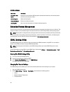
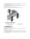
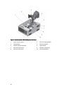
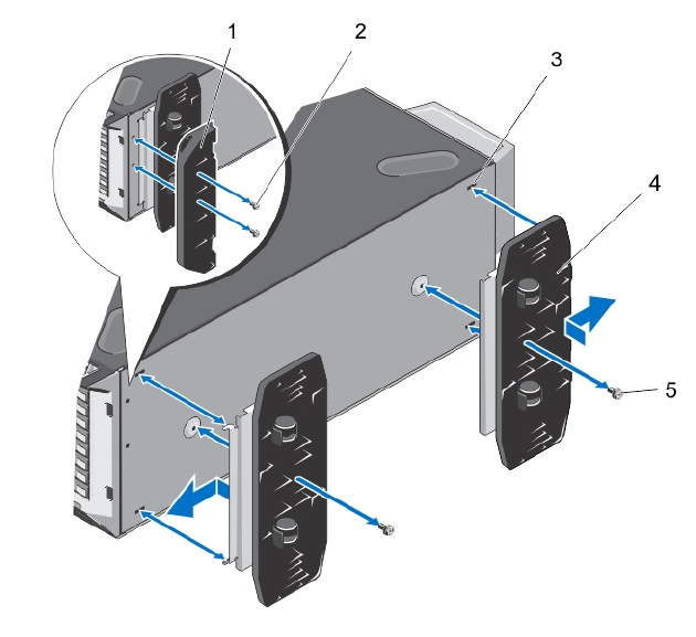
Figure 13. Removing and Installing the Wheel Assembly
1. support unit 2. screws for support unit (2)
3. slots on base of the tower (4) 4. wheel assembly unit (2)
5. screws for wheel assembly (2)
Installing The Wheel Assembly
1. If applicable, rotate the system feet inward.
2. Lay the system on its side on a sturdy, stable surface with the base of the system extending off the edge of the
surface.
3. If applicable, remove the system feet.
4. Align the two retention hooks on the back wheel assembly unit with the two slots on the base of the chassis, and
insert the hooks into the slots.
5. Offset the back wheel assembly slightly to the back of the system and secure the unit in place using a single screw.
6. Align the two retention hooks on the front wheel assembly with the two slots on the base of the chassis, and insert
the hooks into the slots.
43