


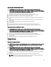
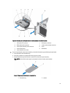
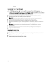
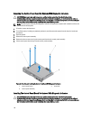
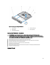
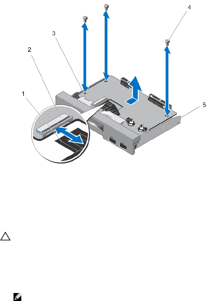
Figure 64. Removing and Installing the Control-Panel Board With LCD Module
1. LCD ZIF cable 2. LCD module ZIF connector
3. control-panel board 4. screws (3)
5. control-panel assembly
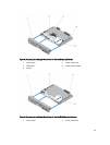
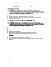
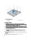
Installing The Control-Panel Board For Systems With LCD Modules
CAUTION: Many repairs may only be done by a certified service technician. You should only perform
troubleshooting and simple repairs as authorized in your product documentation, or as directed by the online or
telephone service and support team. Damage due to servicing that is not authorized by Dell is not covered by your
warranty. Read and follow the safety instructions that came with the product.
1. Using the screw holes, align the control-panel board with the control-panel assembly.
2. Secure the control-panel board to the control-panel assembly using the three screws.
3. Connect the LCD ZIF cable to the LCD module ZIF connector on the control-panel board.
NOTE: The LCD module connector is a ZIF (zero insertion force) connector. Ensure that the locking tab on the
connector is released before removal and insertion. The locking tab must be engaged after insertion.
4. If you are replacing the control-panel board in a system in rack mode, install the VGA module on the control-panel
board.
5. Install the control-panel assembly in the chassis.
6. Close the system.
7. Reconnect the system to its electrical outlet and turn the system on, including any attached peripherals.
8. If applicable, install the front bezel.
115