


3. If applicable, remove the system feet or wheel assembly.
4. Open the system.
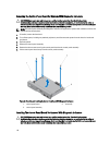
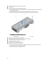
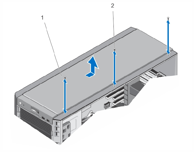
5. Remove the system top cover by following the steps below:
a. Using a #2 Phillips screwdriver, remove the three screws on the side of the system that secure the system top
cover to the system chassis.
b. Slide the top panel toward the back of the system until the panel hooks clear the chassis slots.
c. Rotate the free side of the panel outward about 15 degrees and pull the panel clear of the system.
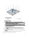
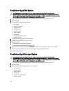
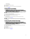
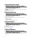
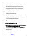
Figure 69. Removing and Installing The System Top Cover
1. system top cover 2. screws (3)
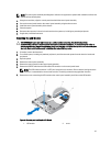
6. Remove the control panel assembly from the chassis.
7. Remove the control panel for tower mode from the control panel assembly.
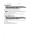
8. Install the VGA module on the control panel assembly.
9. Install the control panel for rack mode.
10. Install the control panel assembly into the chassis.
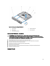
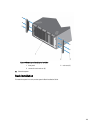
11. To attach the rack ears, follow the steps below:
a. Align the three screw holes on the right rack ear with the screw holes on the right side of the rack system.
b. Install the three screws using a #2 Phillips screwdriver.
c. Repeat step a and step b to install the left rack ear.
124