


3. Open the system.
4. Locate the battery socket.
CAUTION: To avoid damage to the battery connector, you must firmly support the connector while installing
or removing a battery.
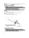
5. To remove the battery, support the battery connector by pressing down firmly on the positive side of the connector.
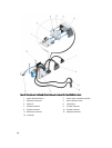
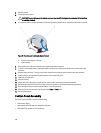
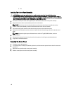
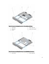
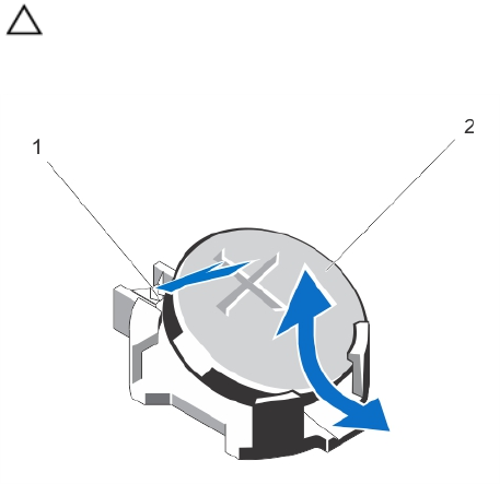
Figure 57. Removing and Installing the System Battery
1. positive side of battery connector
2. system battery
6. Lift the battery out of the securing tabs at the negative side of the connector.
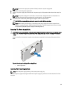
7. To install a new system battery, support the battery connector by pressing down firmly on the positive side of the
connector.
8. Hold the battery with the "+" facing up and slide it under the securing tabs at the positive side of the connector.
9. Press the battery straight down into the connector until it snaps into place.
10. Install the cooling shroud.
11. Close the system.
12. If applicable, place the system upright on a flat, stable surface and turn the system feet outward.
13. Reconnect the system to the electrical outlet and turn the system on, including any attached peripherals.
14. Enter the System Setup to confirm that the battery is operating properly.
15. Enter the correct time and date in the System Setup Time and Date fields.
16. Exit the System Setup.
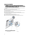
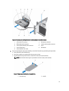
Control-Panel Assembly
The control-panel assembly consists of the following:
• Control-panel board
• Control panel with LCD module or diagnostic indicators
• VGA module (For systems in rack mode only)
108