


78 C2907M-D (4/05)
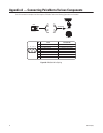
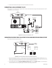
9. Connect one of the three monitor outputs on the rear of the controller to the transmitter.
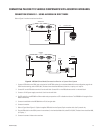
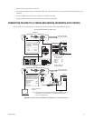
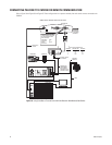
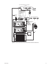
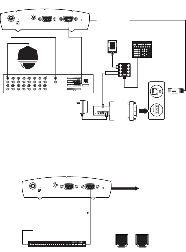
CONNECTING A LOCAL KEYBOARD TO A PC
Refer to Figure 54. This configuration lets an operator control a camera or other external device through a Pelco keyboard attached to a local PC.
(The KBD200A is shown as an example.)
Figure 54. Connecting a Local Keyboard to a PC
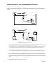
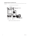
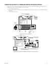
CONNECTING PELCONET COM 1 RS-232 PORT TO THE GENEX MULTIPLEXER COM OUT PORT
Refer to Figure 55 and the instructions that follow.
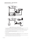
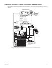
Figure 55. Connecting PelcoNet to Genex Using the COM 1 RS-232 Port
1. Verify that the multiplexer has Version 4.1 or higher software for Genex units manufactured before November 22, 2002or Version 1.12 or
higher for units manufactured on or after that date. (The version numbering was restarted in 2003, which is why newer units have a smaller
version number. The version number flashes on the monitor when power is applied to the multiplexer.)
2. Set the NET350 COM1 data port to Transparent, 9600 baud, 8 data bits, none (for parity), 1 stop bit, and off if it is not so set already. (In
the Interface Mode field on the configuration page for the COM1 interface settings, select RS-232.)
PV140
1
2
3
4
8
7
6
5
12 VAC
KBD200A/
KBD300A
RX-
RX+
STRAIGHT
CABLE
75
Audio I/O
Powe r
NET350
TRANSMITTER
ETHERNET CONNECTION
TO NETWORK (LAN/WAN)
13579
246810
11
12 14
13 15
16
1
2
VIDEOINPUTS
VIDEOOUTPUTS
ALARMS
(1-9 )
ALARMS
(10-18)
COM1 ( 1-6)
COM2 ( 7-12)
CONTROL
OUTPUTS
REMOTE KEYBOARD(S)
LOCAL
KEYBOARD
123456789
10
11
12 13141516 1718
12345678910
11
12
0123
F
2
F
3
N
O
N
C
C
O
M
TT RR
+ +
COM2:
RS232
COM1:
RS232/422/485
Vi deoIn
PC
WORKSTATION
PELCO KEYBOARD
TX-
TX+
RX-
RX+
GND
12 V
12VDC
TRANSMITTER
VideoIn
75
AudioI/O
COM2:
RS232
Power
ETHERNET
CONNECTION
TO NETWORK
PELCONET DB9
CONNECTOR
GENEX COM OUT
RJ-45 CONNECTOR
PIN 2
PIN 3
PIN 5
RX
TX
GND
PIN 6
PIN 4
PIN 5
TX
RX
GND
18 18
GENEX COM
IN OUT
9600, 8, ODD, 1
MULTIPLEXER
COM1:
RS232/422/485