


C2907M-D (4/05) 11
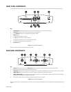
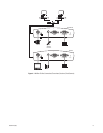
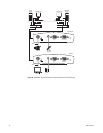
FRONT PANEL COMPONENTS
The PelcoNet NET350 transmission system uses a compact design. For that reason connectors are placed on both the front and rear panels.
Key:
1=
CompactFlash
interface (transmitter only) is a slot for CompactFlash cards and miniature disk drives
2=
Alarm I/O
terminals for alarm input and relay output (refer to Figure 19)
3=RJ-45
Ethernet
connector for connecting to the network (10/100)
4=
Power
socket
5=LED
I
lights red with an active alarm
6=LED
O
lights green when the relay is switched
7=LED
L
lights green when the unit is connected to the network
8=LED
T
flashes yellow when data is transmitted
9=
Hard reset
button
Figure 1.
Front Panel Components
(Refer to the
LEDs
section for more information on the LEDs.)
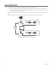
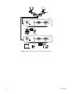
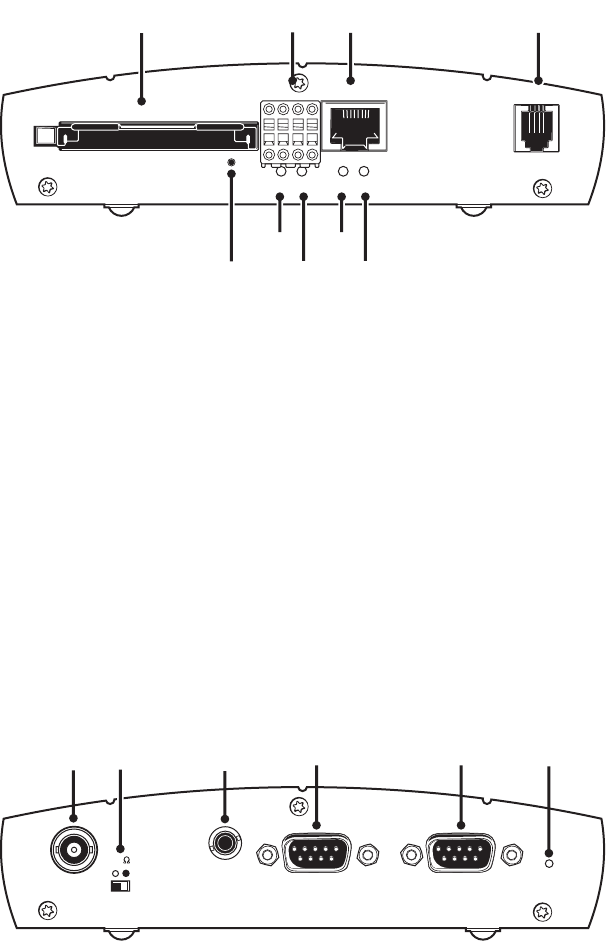
REAR PANEL COMPONENTS
Key:
1=
Video In
BNC socket (transmitter) or
Video Out
BNC socket (receiver) for video source or for an analog video monitor
2=
75
Ω
slide switch (transmitter) for terminating the video input
3=
Audio I/O
bidirectional audio interface; 3.5 mm stereo jack for connecting a loudspeaker or an audio source (monaural line), line level
4=
COM2: RS232
serial interface port; 9-pin male sub-D socket for configuration using terminal software
5=
COM1: RS232/422/485
serial interface port; 9-pin male sub-D socket for controlling data transmissions (RS-232, RS-422, and RS-485
protocols) and for configuration using terminal software
6 = Power LED for device status and software upload failure (refer to the
LEDs
section)
Figure 2.
Rear Panel Components
Refer to the
LEDs
section for more information on the LEDs and to the
Hardware Installation
section for information on interfacing peripherals to
the unit.
Alarm I/O
Ethernet Power
OI
ᕥ
ᕦ
ᕧ
ᕨ
ᕢᕣ ᕤᕡ
ᕩ
CompactFlash
COM2:
RS232
COM1:
RS232/422/485
ᕡ ᕣ ᕤ ᕥ ᕦ
Video In
75
AudioI/O
Power
ᕢ