


26 C2907M-D (4/05)
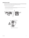
CONNECTING A RELAY
The NET350 has a relay for switching an external device (for example, a light or siren). The relay can be operated from a control page during an
active connection or automatically to coincide with certain events. Settings for the relay must be configured (refer to the
Configuration
section).
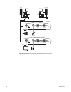
Do the following to connect a peripheral device (such as a light) that can be activated from a PelcoNet live video page. Refer to Figure 19.
1. Pull the Alarm I/O terminal block from its plug-in base.
2. Connect the Alarm Out terminal on the
top
of the block to an external power source and the component to be activated (for example, a light
or buzzer). Then use the second wire to connect the Alarm Out terminal on the
bottom
of the block to the external power source and the
component. (Insert a small screwdriver tip in the square hole and push hard enough to open the corresponding round hole. Insert the wire in
the round hole.)
3. Push the terminal block back on to the plug-in base.
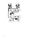
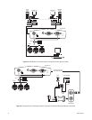
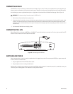
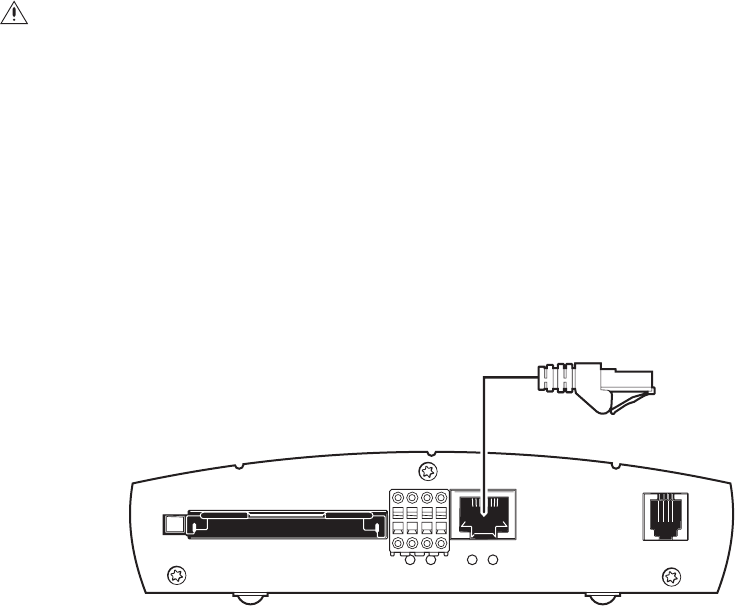
CONNECTING TO A LAN
Refer to Figure 20. You can connect the NET350 to a 10/100BASE-T network either directly or through a hub. To do so, plug a standard Cat5 UTP
cable with RJ-45 connectors into the NET350’s Ethernet socket.
Figure 20.
Connecting to the LAN Port
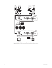
SWITCHING ON POWER
There is no power switch—the unit is ready for operation when it is plugged into an outlet. Do not connect the NET350 to a power source until
all other connections have been made.
1. Plug the supplied cable into the NET350’s Power socket.
2. Plug the adapter end into an outlet grounded to earth.
The Power LED is red during start-up and turns green when the NET350 is ready to operate. If the network connection is established correctly, the
L LED turns green. A flashing yellow T LED means data is moving over the network.
WARNING:
The maximum rating of the relay contact is 30 VDC and 1 A.
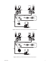
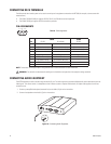
CompactFlash
AlarmI/O
Ethernet Power
LTOI