


C2907M-D (4/05) 77
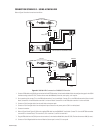
CONNECTION SCENARIO 3 – USING A CM9760-KBD
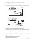
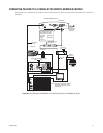
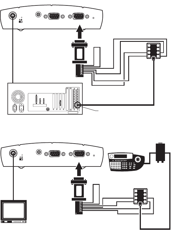
Refer to Figure 53 and the instructions that follow.
Figure 53. CM9760-KBD Connected to a CM9700-CC1 Controller
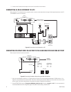
1. Connect a DB9 cable to the COM1 port on the back of the NET350 receiver. (In the Interface Mode field on the configuration page for the COM1
interface settings, select RS-232.) The data format must be 4800baud, 8 data bits, even parity, and 1 stop bit.
2. On the receiver side, connect TX- on the DB9 cable to terminal 7 on the wall block. Connect TX+ on the DB9 cable to terminal 8 on the wall
block. Connect RX- on the DB9 cable to terminal 2 on the wall block. Connect RX+ on the DB9 cable to terminal 1 on the wall block.
3. Connect an RJ-45 straight cable from the wall block to the power pack.
4. Connect an RJ-45 straight cable from the keyboard input connector on the power pack to COM 1 on the keyboard.
5. Connect the monitor.
6. Refer to Figure 50 and Figure 53. Splice the supplied DB9 cable into the CM9760-CC1 wall block. Connect TX- from the NET350 transmitter
to terminal 2 on the wall block, TX+ to terminal 1, RX- to terminal 7, and RX+ to terminal 8.
7. Plug the DB9 cable into the COM1 port on the transmitter. (In the Interface Mode field, select RS-232.) The data format must 4800, 8, even, 1.
8. Connect an RJ-45 flipped cable from the wall block to Sercom port 5 on the CC1’s rear panel.
RECEIVER
VideoIn
75
AudioI/O
COM2:
RS232
COM1:
RS232/422/485
Power
12 VDC
4800, 8, EVEN, 1
FLIPPED
CABLE
TRANSMITTER
PV130
1
2
3
4
8
7
6
5
TX(-)
TX(+)
RX(-)
RX(+)
SERCOM PORT PROGRAMMED FOR KBD
CM9700-CC1
VideoOut
75
AudioI/O
Power
12 VDC
RX(-)
RX(+)
4800, 8, EVEN, 1
STRAIGHT
CABLE
DIRECT
MODE
PV130
1
2
3
4
8
7
6
5
TX(-)
TX(+)
CM9760-KBD
CM9505UPS
COM2:
RS232
COM1:
RS232/422/485