


Preliminary Information MT90840
2-279
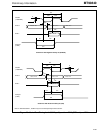
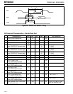
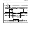
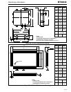
Figure 36 - 84 PLCC Mechanical Drawing
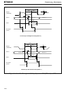
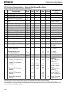
Figure 37 - 100 Pin PQF Mechanical Drawing
F
D
1
D
H
E
1
I
A
1
A
G
D
2
E
E
2
Dim Min Max
A
0.165
(4.20)
0.200
(5.08)
A
1
0.090
(2.29)
0.130
(3.30)
D/E
0.185
(30.10)
1.195
(30.35)
D
1
/E
1
1.150
(29.210)
1.158
(29.413)
D
2
/E
2
1.090
(27.69)
1.130
(28.70)
F
0.026
(0.661)
0.032
(0.812)
G
0.013
(0.331)
0.021
(0.533)
H
0.050 BSC
(1.27 BSC)
I
0.020
(0.51)
Notes:
1) Not to scale.
2) Governing dimensions are in millimeters ().
3) Dimensions in inches are not exact.
4) For D & E add for allowable Mold Protrusion 0.010".
50
1
80
30
81
100
31
51
Pin 1 indicator
E
b
e
L
θ
L1
Notes:
1) Not to scale.
2) Governing dimensions are in millimeters ().
3) Dimensions in inches are not exact.
He
D
Hd
A2
A1
C
Y
Dim Min Max
A
1
0.002
(0.05)
0.02
(0.5)
A
2
0.101
(2.57)
0.113
(2.87)
b
0.008
(0.20)
0.016
(0.40)
c
0.004
(0.10)
0.008
(0.20)
D
0.547
(13.9)
0.555
(14.1)
E
0.783
(19.9)
0.791
(20.1)
e
0.26 nominal
(0.65) nominal
Hd
0.695
(17.65)
0.715
(18.15)
He
0.931
(23.65)
0.951
(24.15)
L
0.025
(10.65)
0.037
(0.95)
L
1
0.077 nominal
(1.95) nominal
Y
0.004
(0.10)
θ
0
(0)
10
(10)