


MT90840 Preliminary Information
2-272
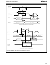
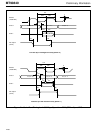
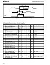
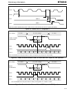
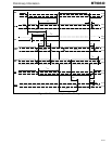
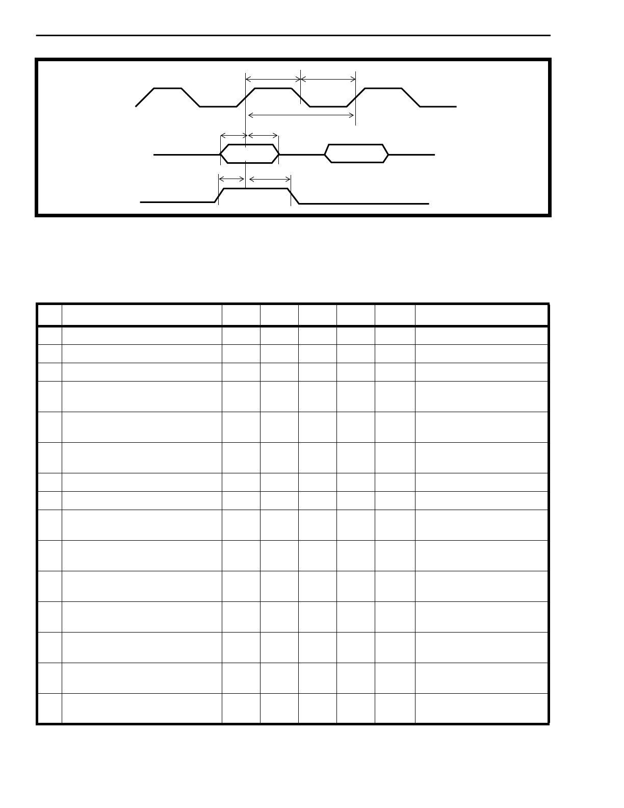
Figure 28 - Parallel Port Receive Timing
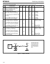
‡ Typical figures are at 25°C and are for design aid only: not guaranteed and not subject to production testing.
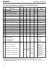
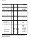
AC Electrical Characteristics - Parallel Data Port
Characteristics Sym Min Typ
‡
Max Units Test Conditions
1 PCKT/PCKR clock period t
clk
50 ns
2 PCKT/PCKR HIGH time
t
clkh
20 ns
3 PCKT/PCKR LOW time
t
clkl
20 ns
4 PPFTo output delay
from PCKR/PCKT transmit edge
t
df
28
30
ns C
L
=30pF
C
L
=50pF
5 PDo output delay
from PCKR/PCKT transmit edge
t
sod
28
30
ns C
L
=30pF
C
L
=50pF
6 CTo0-3 output delay
from PCKR/PCKT transmit edge
t
cdf
26
28
ns C
L
=30pF
C
L
=50pF
7 PDo delay from Active to High-Z
t
za
26 ns C
L
=30pF, R
L
=1K
8 PDo delay from High-Z to Active
t
az
28 ns C
L
=30pF, R
L
=1K
9 PPFRi Setup Time
from PCKR sampling edge
t
frs
5ns
10 PPFRi Hold Time
from PCKR sampling edge
t
frh
8ns
11 PDi Set-up Time
from PCKR sampling edge
t
stis
5ns
12 PDi Hold Time
from PCKR sampling edge
t
stih
8ns
13 PPFTi Input Setup Time
from PCKT sampling edge
t
ppfs
5 ns TM1, PFDI = 1
14 PPFTi Input Hold Time
from PCKT sampling edge
t
ppfh
5 ns TM1, PFDI = 1
15 Jitter between PCKT/PCKR and
C4 serial port clock.
t
pv
-100 +100 ns
C4/8R1 or C4/8R2 at 4.096
MHz with 50% duty cycle
PCKR
t
clkh
t
clk
t
clkl
PDi0-7
t
stis
t
stih
Byte 0
Byte 1
PPFRi
t
fs
t
fh