


MT90840 Preliminary Information
2-248
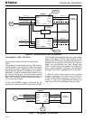
all 16 serial streams can be individually controlled,
so that up to 512 channels can be either transmitted
or received. As an example, if all DC bit locations of
RPCM High are set HIGH, all 512 channels on
STo0-7 and STi0-7 will be configured as outputs. If
all DC bits are LOW, then all 512 channels will be
configured as inputs. In Add/Drop mode all 512
serial channels are copied into the Transmit Path
Data Memory, as inputs, regardless of the DC or OE
bits. This has the effect of a “copy-back” of all serial
outputs.
For more details on per-channel control functions for
the serial and parallel data ports, see the TPCM
High and RPCM High bits definition in the Register
Description section.
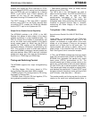
Serial Data Memory Addressing
The serial port mode determines the number of
channels per stream, the number of streams, and the
direction-control operation. Therefore the way in
which serial data is addressed in the internal
memory space must change with the serial port
mode. Because of this, it is necessary to select the
serial port mode (with DR1-0 and FDC in the IMS
register) before programming the Receive Path
Connection Memory.
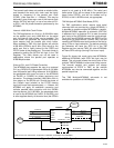
2.048 Mbps Balanced Mode
The 2.048 Mbps Balanced mode has 8 serial input
and 8 serial output streams, and 32 channels per
stream. Therefore 3 bits are used to address the 8
streams, and 5 bits are used to address the 32
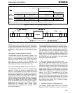
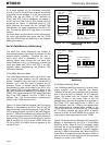
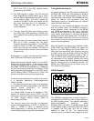
channels. Figure 11a shows how the Transmit Path
Data Memory is read in this mode, by the CPU, or by
the Transmit Path Connection Memory. Each of the
256 input channels is mapped to an address in the
TPDM. CPU reads require the LSB (Least Significant
Bit) of the CAR Register, and the 7 LSBs of the
address bus. The source-channel address-value
written in the TPCM requires 8 bits.
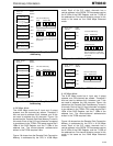
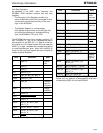
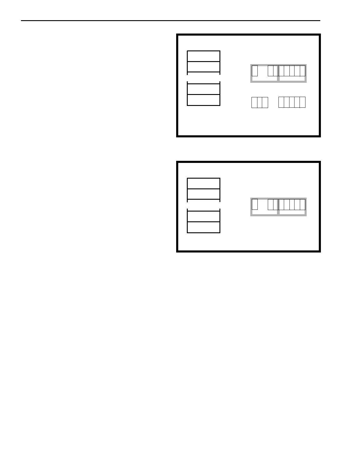
Figure 11b shows how the Receive Path Connection
Memory is addressed by the CPU. Each of the 256
output channels has a control-address in the RPCM.
CPU accesses require the LSB of the CAR Register,
and the 7 LSBs of the address bus. When the DC bit
for a specific output channel is LOW, that channel is
output on the STi pin rather than the STo pin, and the
data at the STo pin is input to the TPDM. When the
DC bit is HIGH, the output channel appears at the
normal STo pin.
Figure 11a - 2.048 Mbps Balanced Mode TPDM
Addressing
Figure 11b - 2.048 Mbps Balanced Mode RPCM
Addressing
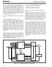
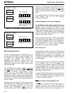
2.048 Mbps Add/Drop Mode
The 2.048 Mbps Add/Drop mode has 16 serial input/
output streams, and 32 channels per stream.
Therefore 4 bits are used to address the 16 streams,
and 5 bits are used to address the 32 channels.
Figure 12a shows how the Transmit Path Data
Memory is read in this mode. Each of the 512
possible input channels is mapped to an address in
the TPDM. CPU reads require the 2 LSBs of the
CAR Register, and the 7 LSBs of the address bus.
The source-channel address-value written in the
TPCM requires 9 bits. In this mode the TPDM reads
all 512 serial channels as inputs. When a specific
channel is driven by the MT90840 as an output, the
output data is also copied back into the TPDM.
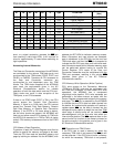
Figure 12b shows how the Receive Path Connection
Memory is addressed by the CPU in 2.048 Mbps
Add/Drop mode. Each of the 512 possible output
channels has a control-address in the RPCM. CPU
accesses require the 2 LSBs of the CAR Register,
and the 7 LSBs of the address bus. When the DC bit
or the OE bit at a specific control-address is LOW, no
data is driven out for that channel, and the input data
at the pin is written to the TPDM.
.
.
STi0, Ch0
STi0, Ch1
000H
001H
CPU Port Addressing:
TPCM Contents:
765
43
21
0
06543
21
0
Stream
Stream
Channel
Channel
Address BusCAR
Bits 7:5 select one of 8 streams.
Bits 4:0 select one of 32
channels per stream.
STi7, Ch30
STi7, Ch31
0FEH
0FFH
Note: Only 256 memory
locations.
Serial Input
Channel
TPDM
Address
.
.
STo0, Ch0
STo0, Ch1
000H
001H
STo7, Ch30
STo7, Ch31
0FEH
0FFH
Note: Only 256 memory locations.
RPCM
Address
Serial Output
Channel
CPU Port Addressing:
06543
21
0
Stream
Channel
Address BusCAR