


58
14. Retrofitting Components
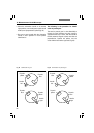
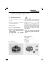
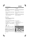
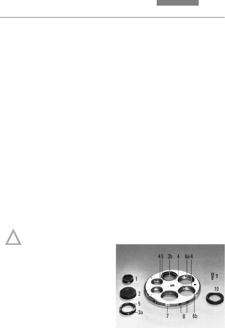
Fig. 57 UCA/P condenser disk
1 Light ring "small, PH"
2 Light ring "large" for large holes
3 a, b DIC condenser prism
4 Marking for assembly of DIC condenser prisms
5 Marking K on the prism mount
6 Guide groove for prism
7 Adhesive label
8 Centering screws
9 Rotatable axis
10 λ or λ/4 compensator
Attention:
Before fitting the disk into the condenser, make
sure that neither of the centering screws is
sticking out at the side.
• Fasten the condenser disk with the axis
screw, check that the disk rotates properly
through 360°
• If present, screw the condenser head into the
condenser and affix the condenser with the
condenser's clamping screw
Condenser UCA/P*
• Unscrew the fastening screw of the disk. This
is found on the underside of the condenser
and must be fully screwed out
• Turn back the centering screws until the light
rings, λ - and λ/4 - compensator* and lens*
2.5x can be inserted;
the largest hole is for brightfield
observation (= BF), the slightly smaller ones
are light rings*, λ - and λ/4 - compensator*
or lens* 2.5x.
Notes:
If you use a smaller hole for brightfield, the
maximum illumination aperture cannot be used.
The lettering (e.g. DF, PH 1 ....., λ) must point
upward, the λ or λ/4 compensators must be
inserted with the correct orientation: The notch
must point toward the center of the disk! The
lettering of the components should
correspond
to
the marking at the opposite position (outer
edge of the disk).
Attention:
Before fitting the disk into the condenser, make
sure that neither of the centering screws is
sticking out at the side.
• Fasten the condenser disk with the axis
screw, check that the disk rotates properly
through 360°
• If present, screw the condenser head into the
condenser and affix the condenser with the
condenser's clamping screw
!!