


49
10. Measurements with the Microscope
10.3 Differentiation of Gout / Pseudo Gout
The use of the lambda plate compensator* is a
prerequisite for this test.
Assembly → p. 24.
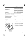
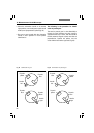
Orienting the Lambda Plate Compensator
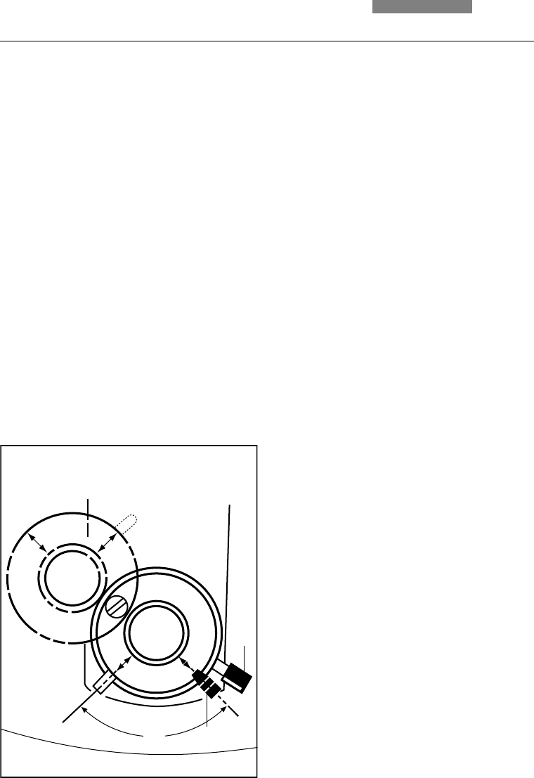
• Rotate the lambda plate compensator out of
light path (fig. 51)
• Bring the lambda plate compensator and
analyzer into cross position until they reach
maximum darkness (polarization → p. 45)
• Fix the cross position thus determined with
the clamping screw at the side (51.2)
• Swing in the lambda plate again
The following section explains the basic
procedure for gout/pseudo gout differentiation.
This test is made possible due to the negative
birefringence of urates and positive birefringence
of pyrophosphates. Both gout (monosodium urate)
and pseudo gout (calcium pyrophosphate) crystals
tend to be needle shaped. However, many
crystals may be broken and/or irregular. To do
the test, it is necessary to find at least one intact
crystal orientated on same axis as orientation
handle and one per-pendicular to axis.
Procedure
To insure the test is being done correctly, a slide
of known monosodium urate crystals should be
used initially.
• Use of a 40x objective is recommended
• Swing the lambda plate out of the path of light
(fig. 51)
• Place the slide on the stage and bring crystals
into a sharp focus; the needle shaped crystals
will appear white regardless of orientation
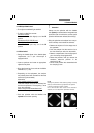
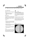
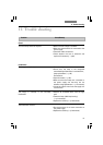
• Swing in the lambda plate and put the
orientation handle (51.1) into it’s extreme left
position; crystals with a long dimension in the
handle direction should appear yellow and
the perpendicular to handle direction blue
(fig. 52)
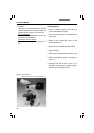
Fig. 51 Lambda plate compensator swung out
1 Orientation handle
2 Clamping screw
2
1
90°