


57
14. Retrofitting Components
14.1 Equipping the Condenser Disk*
• Turn the stage upwards and lower the
condenser
• Remove the condenser by loosening the
condenser’s clamping screw
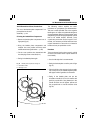
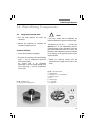
Condenser UCL/UCLP*
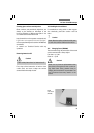
• Loosen the screw (55.1) completely
• Turn back the centering screws until the light
rings*, λ - and λ/4 - compensator* and lens*
2.5x can be inserted;
the largest hole is for brightfield
observation (= BF), the slightly smaller ones
are for light rings, λ - and λ/4 - compensator
or lens* 2.5x
Fig. 55 Condenser UCL
1 Fixing screw for condenser disk
1
14. Retrofitting Components
Notes:
If you use a smaller hole for brightfield, the
maximum illumination aperture cannot be used.
The lettering (e.g. DF, PH 1 ....., λ) must point
upward, the λ or λ/4 compensators must be
inserted with the correct orientation: The notch
must point towards the center of the disk! The
lettering of the components should
correspond
to
the marking at the opposite position (outer
edge of the disk).
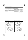
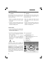
• Tighten the centering screws until the
components are roughly in the center of the
holes
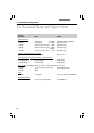
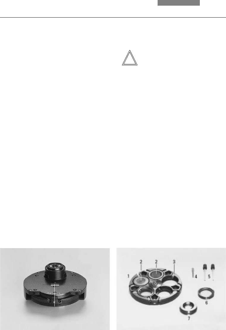
Fig. 56 UCL condenser disk
1 Condenser disk
2 Light ring or λ− or λ/4-compensator
3 Centering screws
4 Axis
5 Centering keys
6 λ- orλ/4-plate
7 Auxiliary lens