


26
6. Assembly
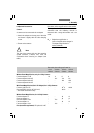
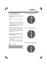
Fig. 22 Tracing device
1 Shutter
Ergomodule*
For raising the eye level of the tube opening, the
30 mm or 60 mm ergomodule may be used.
It is fastened in place with the side clamping
screw.
Installation of the tube on the 60 mm ergo-
module: The tube has to be rotated 90° degree
(eyetubes going to the right) and rotated back
into the viewing position and tightened with the
screw.
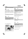
Ergolift*
A base for the stand featuring adjuster wheels
for the base’s height and angle is available to
ensure an optimal working position.
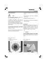
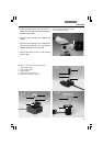
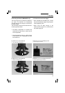
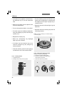
Magnification Changer*
Optionally, a magnification changer (fig. 20) can
be used, which is manually operated. On the
knurled ring, the following magnification factors
can be set:
1x; 1.5x; 2x
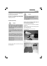
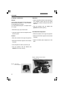
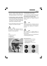
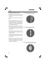
Viewing Attachments*
Viewing attachments featuring illuminated
pointers are available for groups of 2, 3, 4, 5 and
10 viewers respectively (other configurations on
request).
The support (21.3) must be aligned precisely.
The fade-in arrow can be moved in x and y
direction.
Fig. 21 Viewing attachment
1 Movement of light pointer in x and y direction
2 Brightness control
3 Adjustment of arm support
The external power supply (illuminated arrow) is not
illustrated.
Fig. 20 Magnification
changer
1
1
2
3
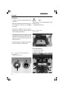
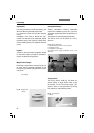
Tracing Device*
The tracing device L3/20 (fig. 22) allows an
optical overlay of large objects (next to the
microscope) on the microscope image. This
makes it easy to draw specimens by tracing
their outlines or superimposing scales.