24
6. Assembly
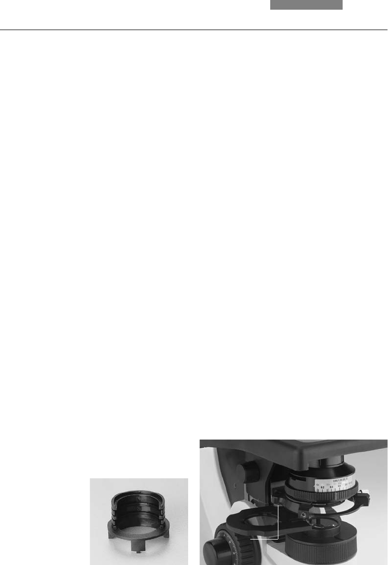
Fig. 19 Assembly of polarizer holder*
1 Clamping screw
1
6.7 Analyzer and Polarizer*
Analyzer
If the analyzer was inserted into the tube mount
before the tube assembly: (→ p. 19), no additio-
nal assembly step is required.
If an intermediate tube pole* or analyzer mount
TL* is used:
• Remove the plug cap on the left side
• Insert the analyzer into the receptacle until it
latches in place
Polarizer
• Raise the condenser to its upper stop position
• Remove the DLF filter magazine from the base
if present
• Press the polarizer holder in place (Fig. 18)
• Push the polarizer with the labeled side
upward into the lower opening
Alternative:
• Attach the polarizer holder to the underside of
the condenser holder with the left clamp
screw (19.1); remove the flip-out blue filter if
required
• Push the polarizer with the labeled side
upward into the lower opening
6.8 Lambda Plate Compensator*
• Raise the condenser to its upper stop position
• Remove the DLF filter magazine from the base
if present
• Attach the lambda plate compensator to the
base
Fig. 18 Filter holder*
with two positions


