


46
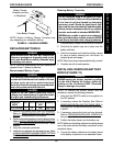
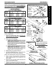
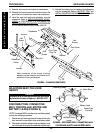
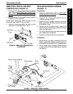
FIGURE 12 - REPLACING MOTOR/GEARBOX
DETAIL "A"
Alignment Pin
Wheelchair
Frame
Alignment
Hole
Long Socket
Screws (Apply
Loctite 242
and torque to
60-inch
pounds)
Short Socket Screws (Apply
Loctite 242 and torque to 60-
inch pounds)
Motor/Gearbox
Support Tube
Underside of Motor
Mount Plate
Motor Mount
Plate
3. Connect the wring harness (BLUE) to the controller
connector (BLUE).
4. Re-secure the wiring harness and motor cables to the
crossbraces with new tie wrap.
5. Reinstall the battery boxes. Refer to
INSTALLING/
REMOVING BATTERY BOXES in this procedure of
the manual.
REPLACING MOTOR/GEARBOX
(FIGURE 12)
1. Remove the battery boxes. Refer to INSTALLING/
REMOVING BATTERY BOXES in this procedure of
the manual.
2. Disconnect the right and/or left motor connector from
the controller.
3. Remove the drive wheels from the wheelchair. Re-
fer to
REPLACING DRIVE WHEELS in PROCE-
DURE 6 of this manual.
4. Remove the six (6) socket screws that secure the mo-
tor/gearbox and support tube to the wheelchair frame.
5. Reposition new motor/gearbox on the wheelchair frame.
6. Position the support tube between the wheelchair
frame and the new motor/gearbox. Make sure the
alignment hole in the support tube is positioned with
the alignment pin on the motor mount plate.
NOTE: The alignment pin is the longest of the three (3) pins
and is located in the center of the wheelchair frame motor
mount plate. Refer to
DETAIL "A"
in
FIGURE 12
.
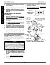
NOTE: When the alignment hole in the support tube is
positioned with the alignment pin on the wheelchair frame,
the anti-tipper wheels should be pointing down towards
the ground/floor.
CAUTION
The longer socket screws must be positioned
in the mounting holes on the OUTSIDE of the
wheelchair frame and the short socket screws
must be in the mounting holes on the INSIDE
of the wheelchair frame. Otherwise damage
to the gearbox casting can result.
7. Use Loctite 242 and securely tighten the support
tube and motor/gearbox to the wheelchair frame
with the six (6) socket screws. Torque to 60-inch
pounds.
8. Reinstall the drive wheels onto the wheelchair.
Refer to
REPLACING DRIVE WHEELS in
PROCEDURE 6 of this manual.
9. Reconnect the right and/or left motor connector
to the controller.
10. Repeat procedure for opposite side of the
wheelchair, if necessary.
11. Reinstall the battery boxes. Refer to
INSTALLING/
REMOVING BATTERY BOXES in this procedure
of the manual.
PROCEDURE 9RWD WHEELCHAIRS
R
W
D
W
H
E
E
L
C
H
A
I
R
S