


27
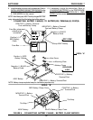
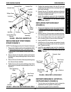
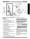
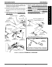
FIGURE 13 - ADJUSTING LIMIT SWITCH
5
o
Seat Angle
24
o
Back
Recline Angle
61
o
Magnetic Protractor -
(Will read 61
o
when back
recline angle is at 114
o
relative to the seat
frame)
Upper Limit
Switch
Bracket
Phillips
Screws,
Washers
and Lock-
nuts
Actuator
114
o
5-3/4 inches
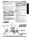
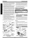
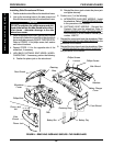
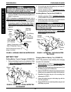
REMOVING/INSTALLING SHROUDS
(FIGURE 14)
Removing Front Shroud
1. Unclip the retaining strap securing the front shroud
and battery box to the wheelchair.
2. Feed the retaining strap through the front shroud.
3. Remove the front shroud from the wheelchair.
Installing Front Shroud
1. Feed the retaining strap through the front shroud as
shown in FIGURE 14.
2. Position the bottom of the front shroud between the
battery box and the battery tray.
3. Clip the retaining strap together.
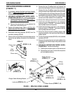
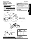
Removing Rear Shroud
1. Unclip the retaining strap securing the rear shroud
and battery box to the wheelchair.
2. Feed the retaining strap through the rear shroud.
3. Remove the rear shroud from the wheelchair.
Installing Rear Shroud
1. Feed the retaining strap through the front shroud as
shown in FIGURE 14.
2. Clip the retaining strap together.
3. Press down on the rear shroud until the two (2) clips
secure the rear shroud to the two (2) side shrouds.
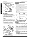
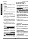
Removing Side Shrouds and Fillers
1. Remove the front shroud from the wheelchair. Refer
to
REMOVING/INSTALLING FRONT SHROUD in
this procedure of the manual.
2. Remove the rear shroud from the wheelchair. Refer
to
REMOVING/INSTALLING REAR SHROUD in this
procedure of the manual.
3. Perform one (1) of the following:
A. INTEGRATED SLING SEAT MODELS - Fold
the wheelchair. Refer to
TRANSPORTING EXCEL
in this procedure of the manual.
B. CAPTAIN'S SEAT MODELS - Remove the
Captain's Seat from the wheelchair. Refer to
REMOVING/INSTALLING CAPTAIN'S SEAT in
PROCEDURE 9 of the owner's manual, part
number 1080737.
4. HIGH BACK CAPTAIN'S SEAT MODEL WHEEL-
CHAIRS ONLY (DETAIL "A") - Remove the phono
jack nut that secures the phono jack to the side shroud.
5. Remove the phillips screws, bolts, washers and lock-
nuts that secure side shroud and filler to the wheel-
chair frame. Refer to FIGURE 14 for phillips screw
and washer locations.
6. Remove side shroud and filler from the wheelchair.
7. Repeat STEPS 5-6 for the opposite side of the wheel-
chair, if necessary.
PROCEDURE 8FWD WHEELCHAIRS
F
W
D
W
H
E
E
L
C
H
A
I
R
S