


37
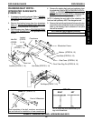
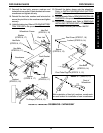
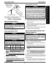
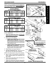
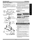
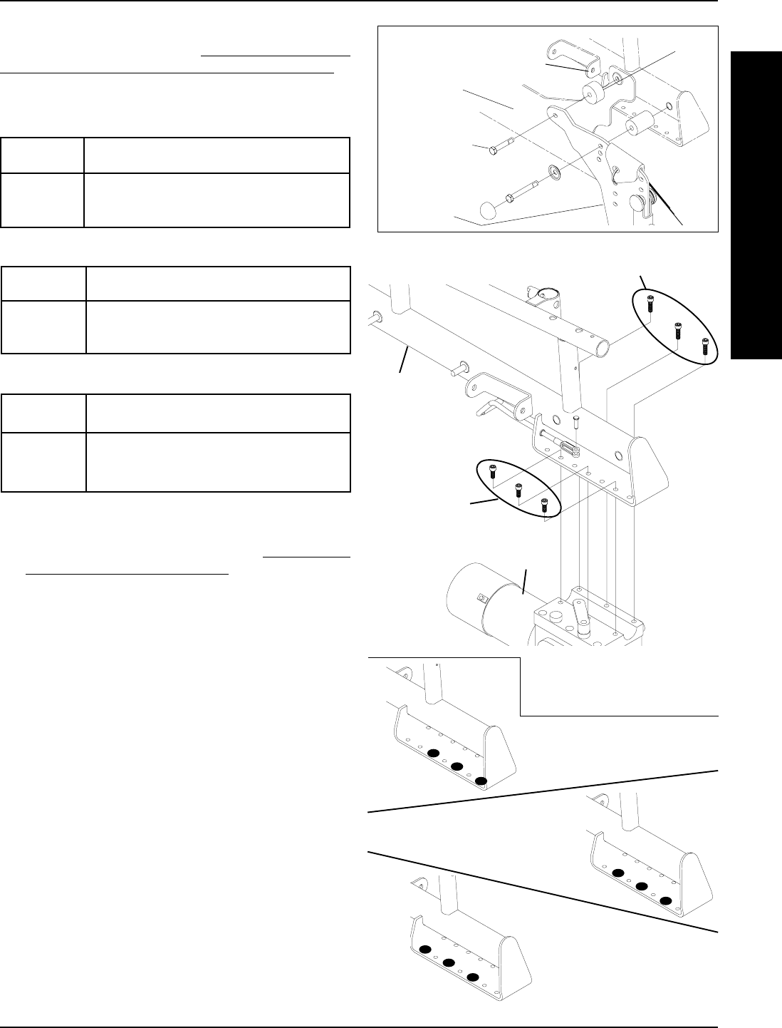
REAR MOTOR
MOUNTING POSITION
MIDDLE MOTOR
MOUNTING POSITION
FRONT MOTOR
MOUNTING POSITION
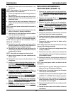
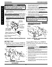
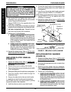
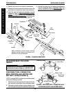
FIGURE 26 - REPOSITIONING MOTORS
Wheelchair
Frame
LONG Socket Screws (Apply Loctite 242 and
torque to 60-inch pounds)
(STEPS 6, 8)
Motor/
Gearbox
SHORT
Socket Screws
(Apply Loctite
242 and
torque to 60-
inch pounds)
(STEPS 6, 8)
STEPS 2, 4, 10, 11, 12
Spacers
Battery Tray
Hanger
Bracket
Hex Screws
Footboard
Mounting
Bracket
NOTE: It is not necessary to
disconnect the clutch handle
from the motor/gearbox.
Dust Cover (Not Shown)
NOTE: If motors are repositioned, the front riggings may
need to be repositioned. Refer to
ADJUSTING/REPLAC-
ING TELESCOPING FRONT RIGGING SUPPORT in
PROCEDURE 9 of the owner's manual, 1080737.
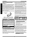
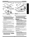
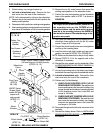
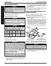
SEAT
WIDTH
16
18
20
SEAT DEPTH
16
MIDDLE
MIDDLE
MIDDLE
17
MIDDLE
MIDDLE
MIDDLE
18
MIDDLE
MIDDLE
MIDDLE
USERS' WEIGHT 201 TO 250 LBS -
MOTOR MOUNTING POSITIONS
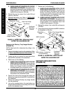
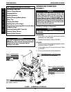
SEAT
WIDTH
16
18
20
SEAT DEPTH
16
REAR
REAR
REAR
17
REAR
REAR
REAR
18
REAR
REAR
REAR
USERS' WEIGHT 200 LBS AND UNDER -
MOTOR MOUNTING POSITIONS
SEAT
WIDTH
16
18
20
SEAT DEPTH
16
MIDDLE
MIDDLE
MIDDLE
17
MIDDLE
MIDDLE
MIDDLE
18
MIDDLE
MIDDLE
MIDDLE
FACTORY SETTINGS
MOTOR MOUNTING POSITIONS
NOTE: The front motor mounting position is reserved
for future applications.
1. Remove the battery boxes. Refer to INSTALLING/
REMOVING BATTERY BOXES in this procedure of
the manual.
2. Perform one (1) of the following:
A. WHEELCHAIR EQUIPPED WITH FLIP-UP
REMOVABLE FOOTBOARD - Remove the hex
screws and spacers that secure the battery tray
hanger bracket and footboard mounting bracket
to the wheelchair frame.
B. WHEELCHAIR NOT EQUIPPED WITH FLIP-UP
REMOVABLE FOOTBOARD - Remove the
front hex screw that secures the battery tray
hanger bracket to the wheelchair frame.
3. Rotate battery tray hanger bracket up.
4. Left side of wheelchair only - Remove the front
dust cover from the end of the crossbrace.
NOTE: Left is determined by sitting in the wheelchair.
5. Refer to charts in this procedure to determine the
proper mounting position that corresponds to the
user's weight.
6. Remove the six (6) socket screws that secure the
motor to the wheelchair frame.
7. Position the motor on the wheelchair frame at the
position noted in STEP 5 as shown in FIGURE 26.
F
W
D
W
H
E
E
L
C
H
A
I
R
S
PROCEDURE 8FWD WHEELCHAIRS