


21
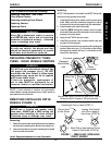
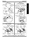
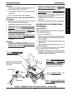
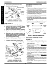
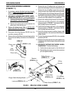
FIGURE 2 - ASSEMBLING EXCEL - UNFOLDING/FOLDING - CAPTAIN'S SEAT
FOLDING.
1. Remove the batteries and footrests/legrests from
the wheelchair. Refer to FIGURE 1.
2. Lift the battery tray UP and out of the way. Refer
to FIGURE 1.
3. Lift up on the seat rails of the wheelchair.
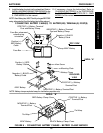
Unfolding/Folding - Captain's Seat (FIGURE 2)
UNFOLDING.
1. Push down on the push brackets until they are flush
with the pivot links on the crossbraces.
2. Assemble the wheelchair. Refer to FIGURE 2.
3. Install the shrouds. Refer to
REMOVING/INSTALLING
SHROUDS in this procedure of the manual.
4. Install the Captain's Seat. Refer to
REMOVING/
INSTALLING CAPTAIN'S SEAT in PROCEDURE 9
of the owner's manual, part number 1080737.
5. HIGH BACK CAPTAIN'S SEATS ONLY - Connect
the limit switch. Refer to
DISCONNECTING/
CONNECTING LIMIT SWITCH in this procedure of
the manual.
FOLDING.
1. HIGH BACK CAPTAIN'S SEATS ONLY - Disconnect
the limit switch. Refer to
DISCONNECTING/
CONNECTING LIMIT SWITCH
in this procedure of
the manual.
Refer to
INSTALLING/REMOVING
BATTERY BOXES in this procedure
of the manual.
Refer to BATTERY TRAY in this
procedure of the manual.
Refer to
PREPARING MKIV
JOYSTICK FOR USE in PRO-
CEDURE 5 of this manual.
Refer to
INSTALLING/REMOVING
FOOTRESTS or INSTALLING
ELEVATING LEGRESTS in
PROCEDURE 3 of the owner's
manual, part number 1080737.
Refer to REPOSITIONING
MOTORS in this procedure of
the manual.
Push Brackets
Crossbraces
2. Remove the Captain's Seat. Refer to REMOVING/
INSTALLING CAPTAIN'S SEAT in PROCEDURE 9
of the owner's manual, part number 1080737.
3. Remove the shrouds. Refer to
REMOVING/INSTALL-
ING SHROUDS in this procedure of the manual.
4. Remove the batteries and footrests/legrests from the
wheelchair. Refer to FIGURE 2.
5. Lift the battery tray UP and out of the way. Refer to
FIGURE 2.
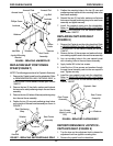
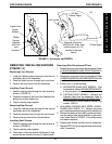
6. Lift up on push brackets located on the crossbraces.
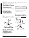
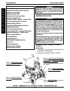
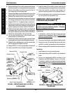
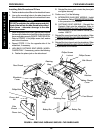
ADJUSTING FLIP-UP REMOVABLE
FOOTBOARD
Angle (FIGURE 3)
NOTE: Angle availability is limited when the motors are
in the forward-most position.
1. Remove the caplug caps.
2. Remove the front hex screw and caplug washer that
secure the footboard mounting bracket and bushing
to the wheelchair.
3. Repeat STEP 2 for the opposite front hex screw and
caplug washer.
4. Move the footboard mounting brackets to one (1) of
three (3) positions.
NOTE: To ensure the existing hex screws tighten
securely, apply Loctite 242 onto the threads.
5. Reinstall the two (2) hex screws and caplug washers
through the two (2) footboard mounting brackets and
bushings and into the wheelchair.
PROCEDURE 8FWD WHEELCHAIRS
F
W
D
W
H
E
E
L
C
H
A
I
R
S
Pivot Link