


25
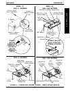
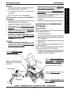
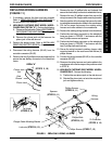
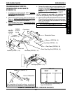
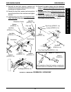
6. Remove the two (2) phillips bolts and locknuts that
secure the front battery connector to wheelchair frame.
7. Remove the two (2) phillips screws that secure the
wiring harness to the charger cable mounting bracket.
8. Note the position of the tie wraps that secure the exist-
ing wiring harness and motor cables to the crossbraces.
9. Cut the tie wraps that secure the existing wiring
harness and motor cables to the crossbraces.
10. Remove the existing wiring harness from wheelchair.
11. Position the rear battery connector on the wheelchair
frame as shown in FIGURE 11 and secure with the
two (2) phillips screws and spacers.
12. Position the front battery connector on the wheelchair
frame as shown in FIGURE 11 and secure with the
two (2) phillips bolts and locknuts.
13. Secure the wiring harness to existing charger cable
mounting bracket on the seat frame with the two (2)
phillips screws.
14. Connect the wiring harness (BLUE) to the controller
connector (BLUE).
15. Resecure the wiring harness and motor cables to the
crossbraces with new tie wraps at the positions noted
in STEP 8.
16. HIGH BACK CAPTAIN'S SEAT MODEL WHEEL-
CHAIRS ONLY - Perform the following:
A. Position the new phono jack on the side shroud.
B. Reinstall the phono jack nut onto the new phono
jack and tighten securely.
REPLACING WIRING HARNESS
(FIGURE 11)
1. If necessary, remove the front and rear shrouds.
Refer to
REMOVING/INSTALLING SHROUDS in
this procedure of the manual.
2. HIGH BACK CAPTAIN'S SEAT MODEL WHEEL-
CHAIRS ONLY (DETAIL "A") - Perform the following:
A. Disconnect the limit switch. Refer to
DISCONNECT-
ING/CONNECTING LIMIT SWITCH in this proce-
dure of the manual.
B. Remove the phono jack nut that secures the
phono jack to the side shroud.
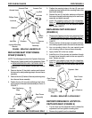
3. Remove the battery boxes. Refer to
INSTALLING/
REMOVING BATTERY BOXES in this procedure of
the manual.
4. Disconnect the wiring harness (BLUE) from the
controller connector (BLUE).
5. Remove the two (2) phillips screws and spacers that
secure the rear battery connector to the wheelchair
frame.
FIGURE 11 - REPLACING WIRING HARNESS
DETAIL "A"
(STEPS 2, 16)
Phono Jack
Nut
Phono Jack
Side
Shroud
Tie Wraps
(STEPS 8, 15)
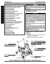
PROCEDURE 8
FWD WHEELCHAIRS
F
W
D
W
H
E
E
L
C
H
A
I
R
S
Charger Cable Mounting Bracket
Wiring
Harness
To Controller
(STEPS 4, 14)
Phillips Screws
(STEPS 7, 13)
Spacers
(STEPS 5, 11)
Locknuts
(STEPS 6, 12)
Phillips Bolts
(STEPS 6, 12)
Phillips Screws
(STEPS 5, 11)