


26
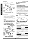
C. Connect the limit switch. Refer to DISCONNECT-
ING/CONNECTING LIMIT SWITCH in this
procedure of the manual.
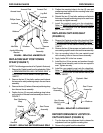
17. Reinstall the battery boxes. Refer to
INSTALLING/
REMOVING BATTERY BOXES in this procedure of
the manual.
18. If necessary, install the front and rear shrouds. Refer
to
REMOVING/INSTALLING SHROUDS in this pro-
cedure of the manual.
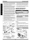
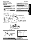
DISCONNECTING/CONNECTING
LIMIT SWITCH (FIGURE 12)
NOTE: The following procedure is for High Back Captain's
seat model wheelchairs only.
CAUTION
Disconnect limit switch BEFORE removing seat or
damage to switch may occur.
1. Perform one (1) of the following:
DISCONNECTING - While holding the body of
the limit switch phono plug,
lift up gently.
NOTE: When the limit switch is unplugged the wheel-
chair will NOT operate.
CONNECTING - Plug limit switch plug into the
limit switch phono jack.
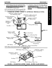
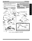
FIGURE 12 - DISCONNECTING/CONNECTING LIMIT
SWITCH
Limit
Switch
Phono
Plug
Body
Limit Switch
Phono Jack
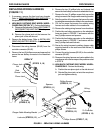
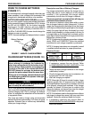
ADJUSTING LIMIT SWITCH
(FIGURE 13)
NOTE: The following procedure is for High Back Captain's
seat model wheelchairs only.
WARNING
NEVER operate the wheelchair while in any re-
cline position over 114
o
RELATIVE TO THE SEAT
FRAME. If the limit switch does not stop the wheel-
chair from operating in a recline position greater
than 114
o
RELATIVE TO THE SEAT FRAME, DO NOT
operate the wheelchair. Adjust the limit switch or
have the wheelchair serviced by a dealer or
qualified technician, otherwise injury or damage
may occur.
1. Place the wheelchair on a level surface.
2. Recline the captain's seat back to a 24
o
to achieve the
114
o
angle relative to the seat frame. Refer to AD-
JUSTING CAPTAIN'S SEAT in PROCEDURE 9 of
the owner's manual, part number 1080737.
NOTE: The captain's seat frame is at a 5
o
angle relative to
the ground. When the back angle is adjusted to 114
o
rela-
tive to the seat, it will measure 61
o
relative to the ground.
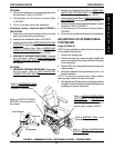
NOTE: To determine 114
o
back angle relative to the seat
frame, place a magnetic protractor (available at any hard-
ware store) on the back as shown in FIGURE 13 and
adjust the back until the magnetic protractor reads 61
o
.
3. Turn the wheelchair power switch on the joystick to
the ON position.
NOTE: The wheelchair should not operate.
4. IF wheelchair operates, proceed to the following steps
to adjust the actuator on the upper limit switch bracket:
A. Fully recline the back. Refer to
ADJUSTING
CAPTAIN'S SEAT in PROCEDURE 9 of the
owner's manual, part number 1080737.
NOTE: This will make access to limit switch easier.
B. Loosen, but do not remove, the two (2) phillips
screws, washers and locknuts that secure the
actuator to the upper limit switch bracket.
C. Slide actuator UP (towards top of the wheelchair).
CAUTION
DO NOT over tighten the phillips screws that
secure the actuator to the upper limit switch
bracket. Damage to the actuator may occur.
D. Only tighten the two (2) phillips screws, washers
and locknuts that secure the actuator to the up-
per limit switch bracket until the actuator does
not move.
E. Repeat STEPS 1-3 until wheelchair does not
operate when captain's seat back is at a 24
o
angle.
PROCEDURE 8 FWD WHEELCHAIRS
F
W
D
W
H
E
E
L
C
H
A
I
R
S