


36
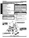
PROCEDURE 8 FWD WHEELCHAIRS
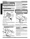
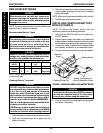
B. WHEELCHAIR NOT EQUIPPED WITH FLIP-UP
REMOVABLE FOOTBOARD - Reinstall the front
hex screw that secures the new right battery tray
hanger bracket to the wheelchair frame. Use
Loctite 242 and torque to 156-in/lbs.
8. Reinstall the rear hex screw. Use Loctite 242 and
torque to 156-in/lbs.
9. Reinstall the battery tray. Refer to INSTALLING
BATTERY TRAY in this procedure of the manual.
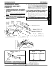
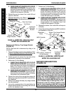
FIGURE 24 - BATTERY TRAY - REPLACING RIGHT
BATTERY TRAY HANGER BRACKET
Rear Hex Screw
Hex Screw
Battery Tray
Hanger Bracket
Footboard
Mounting
Bracket
Spacer
Wheelchair Frame
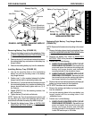
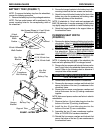
7. Perform one (1) of the following:
A. WHEELCHAIR EQUIPPED WITH FLIP-UP
REMOVABLE FOOTBOARD - Reinstall the hex
screw and spacer that secures the new left
battery tray hanger bracket and footboard
mounting bracket to the wheelchair frame. Use
Loctite 242 and torque to 156-in/lbs.
B. WHEELCHAIR NOT EQUIPPED WITH FLIP-UP
REMOVABLE FOOTBOARD - Reinstall the front
hex screw that secures the new left battery tray
hanger bracket to the wheelchair frame. Use
Loctite 242 and torque to 156-in/lbs.
8. Reinstall the locknut. Use Loctite 242 and torque to
156-in/lbs.
9. Torque the rear locknut that secures MKIV controller to
the wheelchair to 156-in/lbs.
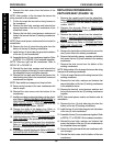
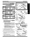
FIGURE 25 - BATTERY TRAY - REPLACING LEFT
BATTERY TRAY HANGER BRACKET
MKIV Controller
Rear Locknut - Loosen, but
Do Not Remove
Locknut
Battery Tray Hanger Bracket
Footboard
Mounting
Bracket
Hex Screw
Spacer
Wheelchair
Frame
Replacing Left Battery Tray Hanger Bracket
(FIGURE 25)
NOTE: Right and left is determined by sitting in the
wheelchair.
1. Remove the battery boxes from the wheelchair. Refer
to
INSTALLING/REMOVING BATTERY BOXES in this
procedure of the manual.
2. Loosen, but do not remove the rear locknut that
secures MKIV controller to the wheelchair.
3. Perform one (1) of the following:
A. WHEELCHAIR EQUIPPED WITH FLIP-UP
REMOVABLE FOOTBOARD - Remove the hex
screw and spacer that secures the existing left
battery tray hanger bracket and footboard
mounting bracket to the wheelchair frame.
B. WHEELCHAIR NOT EQUIPPED WITH FLIP-UP
REMOVABLE FOOTBOARD - Remove the front
hex screw that secures the existing left battery
tray bracket to the wheelchair frame.
4. Remove the locknut that secures the existing left
battery tray hanger bracket and MKIV controller from
the wheelchair.
5. Remove the existing left battery tray hanger bracket
from the wheelchair.
6. Line up the mounting holes in the new battery tray
hanger bracket with the front mounting hole and rear
stud on the wheelchair frame.
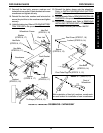
REPOSITIONING MOTORS
(FIGURE 26)
WARNING
The overall performance of the wheelchair WILL
be affected by the front wheel mounting
position. The following charts show the mounting
position of the motors for each seat width and
depth depending on the factory setting or user's
weight. If the mounting position that corresponds
to the user's weight is different than the factory
setting, the motors MUST BE repositioned to
maintain proper stability BEFORE using the wheel-
chair. Otherwise injury or damage may occur.
Periodically review the following charts to make
sure the motor mounting position still corresponds
to the user's weight to maintain the proper stability.
F
W
D
W
H
E
E
L
C
H
A
I
R
S