


43
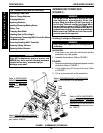
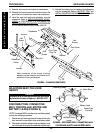
2. Secure the hanger brackets to the battery tray in the
mounting holes that the hex screws are mounted.
3. Attach the key slot bracket located at the front of the
battery tray over the crossbrace bolt bushing under
the seat upholstery of the wheelchair.
NOTE: If wheelchair is 14-inch wide and equipped with
MKIV RII electronics, it may be necessary to turn battery
tray slightly away from controller to install the battery tray.
4. Attach the hanger brackets to the support tubes on
the wheelchair frame.
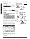
CHANGING SEAT WIDTH
(FIGURE 8)
1. Remove the battery boxes and battery tray from the
wheelchair. Refer to
INSTALLING/REMOVING
BATTERY BOXES and INSTALLING/REMOVING
BATTERY TRAY in this procedure of the manual.
2. Remove the existing back and seat upholstery from
the wheelchair. Refer to
REPLACING BACK
UPHOLSTERY in PROCEDURE 3 of this manual and
REPLACING SEAT UPHOLSTERY in PROCEDURE
5 of the owners manual, part number 1080737.
NOTE: If adjusting the seat width of the wheelchair, the
back and seat upholstery MUST be changed as well.
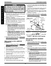
3. Remove the hex screws and locknuts that secure the
two (2) pivot links to the wheelchair frame and cross-
braces. Refer to the following chart to determine if
new pivot links will be needed:
PIVOT LINK SEAT WIDTH RANGE (IN INCHES)
14-15, 16-18 and 19-20
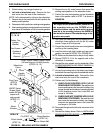
4. Remove dust covers from bottom of crossbraces.
5. Remove the hex screws, washers and locknuts that
secure the bottom of the two (2) crossbraces to the
wheelchair frame.
6. Remove the hex screw, coved spacers, washers and
locknut that secure the two (2) existing crossbraces
together.
NOTE: Note coved spacer, washer and locknut order for
reinstallation.
7. Remove the four (4) pivot tube plug pins from the
bottom of the two (2) existing crossbraces.
8. Install the four (4) pivot tube plug pins into the
bottom of the two (2) new crossbraces.
9. Assemble the two (2) new crossbraces together.
Refer to FIGURE 8 for hardware orientation.
10. Reinstall the hex screws, washers and locknuts that
secure the bottom of the two (2) new crossbraces to
the wheelchair frame.
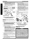
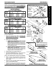
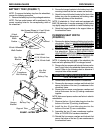
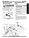
BATTERY TRAY (FIGURE 7)
NOTE: To remove the battery tray from the wheelchair,
reverse the following procedure.
1. Remove the battery tray from the packaged container.
NOTE: The hex socket screws will be positioned in the
correct mounting holes for the corresponding width of
the wheelchair.
Battery Tray
Hanger
Bracket
Support Tube
Crossbrace
Bolt Bushing
Battery Tray
Key Slot
Bracket
FIGURE 7 - BATTERY TRAY
Hex Screws (Shown in 14 and 16-inch
Wheelchair Width positions)
18-inch
Wheelchair
Width
Position
20-inch Wheelchair
Width Position
Locknut
Locknut
14-inch Adult
16, 18, 20-inch Low
16, 18, 20-inch Adult
Key Slot
Bracket
R
W
D
W
H
E
E
L
C
H
A
I
R
S
PROCEDURE 9RWD WHEELCHAIRS