


44
PROCEDURE 9 RWD WHEELCHAIRS
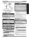
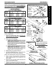
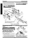
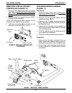
FIGURE 8 - CHANGING SEAT WIDTH
Locknut
Wheelchair
Frame
Hex
Screw
Locknut
Pivot Link
Hex
Screws
Washer
Dust Cover
Crossbrace
Note orientation of hex screw, bushing,
washers, coved washers and locknut for in-
stallation of new crossbraces.
14. Reinstall the battery tray and battery boxes/batteries
onto the wheelchair. Refer to
BATTERY TRAY and
INSTALLING/REMOVING BATTERY BOXES in this
procedure of the manual.
ADJUSTING SEAT-TO-FLOOR
HEIGHT
WARNING
Adjusting seat-to-floor height MUST be performed
by Invacare Technical Support, 1-800-832-4707.
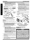
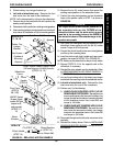
DISCONNECTING/CONNECTING
MKIV CONTROLLER, MOTOR AND
BATTERY LEADS (FIGURE 9)
NOTE: To connect MKIV controller motor and battery leads,
reverse the following procedure.
1. Disconnect the fastening straps that secure the nylon
boot around the connected motor and battery leads.
2. Disconnect controller left/right motor and battery leads
from the leads secured to the wheelchair with tie wrap.
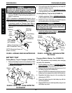
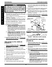
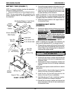
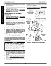
FIGURE 9 - DISCONNECTING/CONNECTING MKIV
CONTROLLER, MOTOR AND BATTERY LEADS
Nylon Boot
Battery Lead
Left/Right Motor
Leads
Leads From
Controller
Fastening Straps
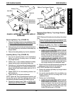
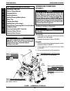
11. Reinstall dust covers onto bottom of crossbraces.
12. Reinstall the hex screws and locknuts that secure the
pivot links to the wheelchair frame and crossbraces.
13. Install the new back and seat upholstery onto the
wheelchair. Refer to
REPLACING BACK UPHOL-
STERY in PROCEDURE 3 of this manual and
REPLACING SEAT UPHOLSTERY in PROCEDURE
5 of the owners manual, part number 1080737.
Pivot Tube
Plug Pin
Hex
Screws
R
W
D
W
H
E
E
L
C
H
A
I
R
S