


29
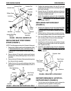
CHANGING SEAT WIDTH -
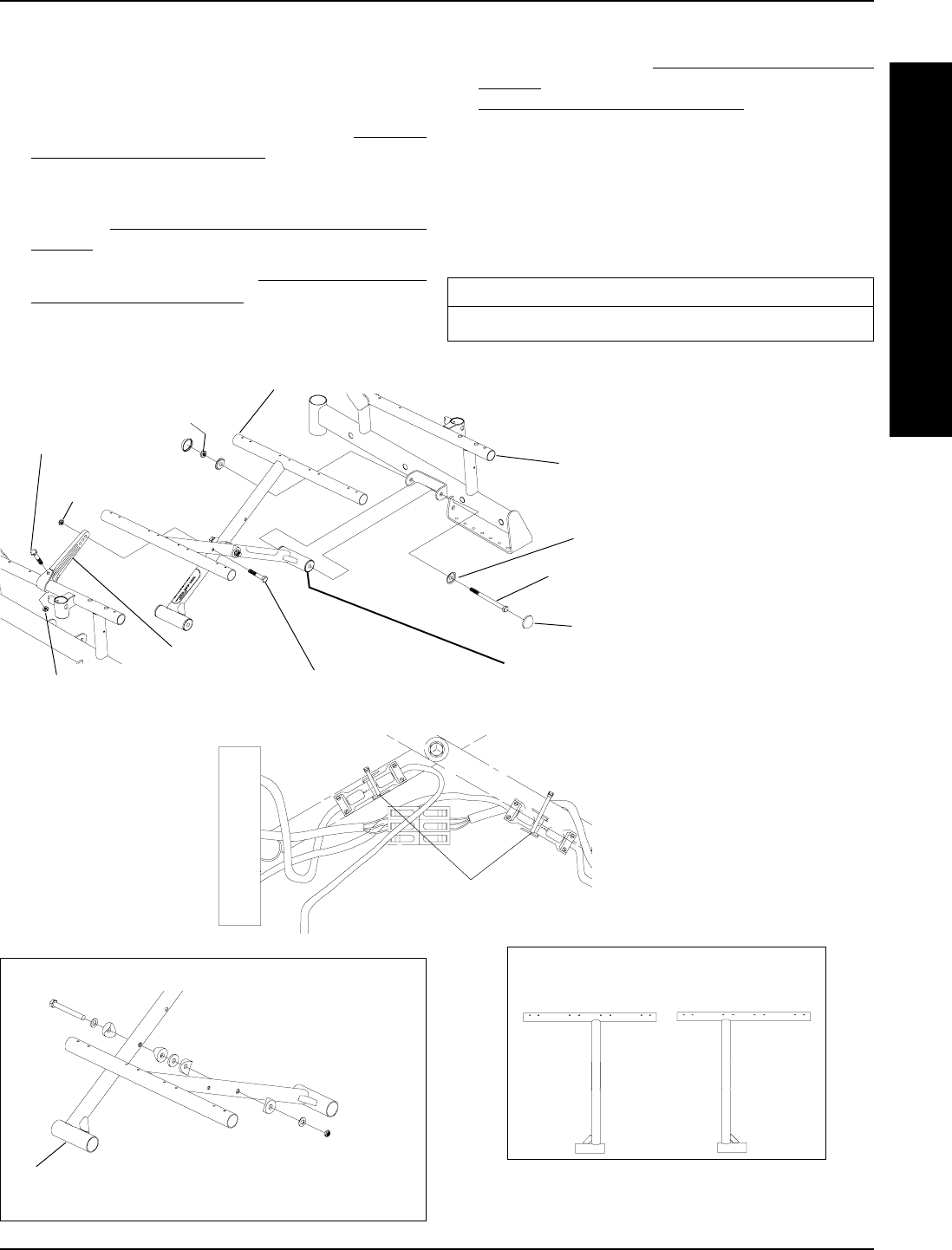
INTEGRATED SLING SEATS
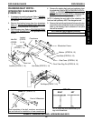
(FIGURE 15)
1. If necessary remove the shrouds. Refer to REMOV-
ING/INSTALLING SHROUDS in this procedure of
the manual.
2. Remove the battery boxes from the wheelchair.
Refer to
INSTALLING/REMOVING BATTERY
BOXES in this procedure of the manual.
3. Fold the battery tray. Refer to
FOLDING BATTERY
TRAY FOR TRANSPORT in this procedure of the
manual.
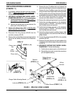
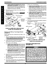
Locknut
(STEPS 5, 14)
Hex Bolt
(STEPS
5, 14)
Locknut
(STEPS 5, 14)
Pivot Link
Dust Cover
(STEPS 6, 16)
Wheelchair Frame
Hex Bolts
(STEPS 5, 14)
Washer
(STEPS 8, 13)
Crossbrace
Locknut
(STEPS
8, 13)
Hex Bolts
(STEPS 8, 13)
DETAIL "B"
FIGURE 15 - CHANGING SEAT WIDTH - INTEGRATED SLING SEAT S
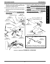
NOTE: Right and left is determined by sit-
ting in the wheelchair.
RIGHT LEFT
Note orientation of hex bolt, washers, coved wash-
ers and locknut for installation of new crossbraces.
Front of Wheelchair
DETAIL "A" - (STEPS 9, 12)
Pivot Tube Plug Pin
(STEPS 9, 10)
Tie Wraps
(STEPS 7, 15)
4. Remove the existing back and seat upholstery from
the wheelchair. Refer to
REPLACING BACK UPHOL-
STERY in PROCEDURE 5 of this manual and
REPLACING SEAT UPHOLSTERY in PROCEDURE
5 of the owner's manual, part number 1080737.
NOTE: If adjusting the seat width of the wheelchair, the
back and seat upholstery MUST be changed as well.
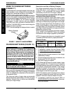
5. Remove the hex bolts and locknuts that secure the two
(2) pivot links to the wheelchair frame and crossbraces.
Refer to the following chart to determine if new pivot
links will be needed:
PIVOT LINK SEAT WIDTH RANGE (in inches)
16-18 or 20
PROCEDURE 8FWD WHEELCHAIRS
F
W
D
W
H
E
E
L
C
H
A
I
R
S