


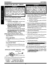
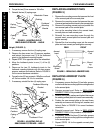

22
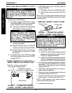
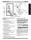
Flip Up Footboard
Caplug
Cap
Washer
Hex
Screw
Locknut
Footboard Mounting
Bracket
Height (FIGURE 4)
1. If necessary, remove the four (4) caplug caps.
2. Remove the hex screw, two (2) spacers, washers
and locknut that secure one (1) of the footboard
pivots to the footboard mounting bracket.
3. Repeat STEP 2 for opposite side of the wheelchair.
4. Move the footboard pivots to one (1) of five (5)
positions.
5. Resecure the two (2) footboard pivots to the
footboard mounting brackets with the hex screws,
spacers, washers and locknuts. Refer to FIGURE 4
for the correct hardware orientation.
6. Torque the two (2) hex screws to 156in/lbs. and back
off the hex screws 1/8-1/4 of a revolution.
7. If necessary, reinstall the four (4) caplug caps.
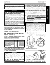
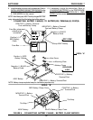
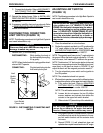
FIGURE 3 - ADJUSTING FLIP-UP
REMOVABLE FOOTBOARD - ANGLE
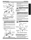
Caplug
Cap
Hex
Screw
Caplug
Washer
Wheelchair Frame
Footboard
Mounting
Bracket
Bushing
Five (5)
Mounting
Positions
Footboard Pivot
FIGURE 4 - ADJUSTING FLIP-UP
REMOVABLE FOOTBOARD - HEIGHT
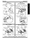
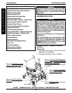
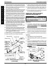
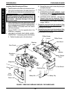
REPLACING ARMREST PADS
(FIGURE 5)
1. Remove the mounting screws that secures the front
of the armrest pad to the armrest plate.
2. Remove the mounting screw that secures the rear
of armrest pad and armrest insert to the armrest plate.
3. Remove the existing armrest pad and position the
new armrest pad on the armrest plate.
4. Line up the mounting holes in the armrest insert,
armrest plate and new armrest pad.
5. Reinstall the rear mounting screw through the
armrest insert, armrest plate and armrest pad and
tighten securely.
6. Reinstall the front mounting screw into the armrest
plate and new armrest pad and tighten securely.
Armrest
Insert
Mount-
ing
Screw
Armrest
Pad
Armrest Plate
FIGURE 5 - REPLACING ARMREST PADS
Mounting
Screw
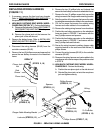
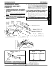
REPLACING ARMREST PLATE
(FIGURE 6)
1. If necessary, remove the three (3) hex bolts, spacers
and locknuts that secure the joystick mounting bracket
to the armrest plate.
2. Remove armrest pad. Refer to
REPLACING
ARMREST PADS in this procedure of the manual.
3. Remove the lug bolt, washers and locknut that secure
the existing armrest plate to the seat frame assembly.
4. Position the new armrest plate on the seat frame
assembly and secure with the lug bolt, washers and
locknut. Refer to FIGURE 2 for correct hardware
orientation.
5. Reinstall armrest pad. Refer to
REPLACING
ARMREST PADS in this procedure of the manual.
6. If necessary, reinstall the three (3) hex bolts, spacers
and locknuts that secure the joystick mounting bracket
to the armrest plate.
7. Repeat STEPS 1-6 for the opposite armrest plate,
if necessary.
FRONTREAR
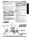
PROCEDURE 8 FWD WHEELCHAIRS
F
W
D
W
H
E
E
L
C
H
A
I
R
S
6. Torque the two (2) hex screws to 156-in/lbs.
7. Reinstall the two (2) caplug caps.