


18
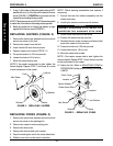
Battery Cable
Battery Clamp
Cover
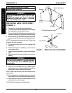
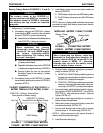
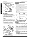
2. Install battery clamp covers onto battery cables as
follows (FIGURE 5):
A. RED battery clamp cover onto RED battery cable.
B. BLACK battery clamp cover onto BLACK battery
cable.
NOTE: Only one (1) battery cable and battery clamp cover
are shown for clarity. Both battery clamp covers install in
the same manner.
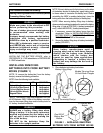
Battery Clamp Method (FIGURES 4, 5 and 6).
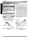
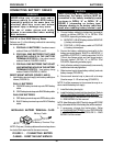
WARNING
The battery clamp of the POSITIVE (+)
battery terminal/post MUST be mounted in
the position shown in FIGURE 5, otherwise
the battery box top cannot be installed
properly.
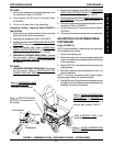
1. Perform one (1) of the following:
A. If the battery clamp of the POSITIVE (+) battery
terminal/post is NOT mounted in the orientation
shown in FIGURE 5, perform the following:
● Loosen the hex nut that secures the battery clamp
to the POSITIVE (+) battery terminal/post.
CAUTION
When tightening the clamps,
always use a box wrench. Pliers will
“round off” the nuts. NEVER wiggle
the battery terminal(s)/post(s)
when tightening. The battery may
become damaged.
● Remove the battery clamp from the POSITIVE
(+) battery terminal/post.
● Reposition the battery clamp on the POSITIVE
(+) battery terminal/post as shown in FIGURE 4.
● Securely tighten the hex nut that secures
the battery clamp to the positive (+) battery
terminal/post.
B. If the battery clamp on the POSITIVE (+) battery
terminal/post is positioned as shown in FIGURE 4,
proceed to STEP 2.
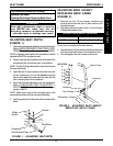
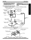
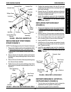
NEGATIVE (-) Battery
Terminal/Post and Battery Clamp
POSITIVE (+) Battery Terminal/Post
(Note position of battery clamp)
FIGURE 4 - CONNECTING BATTERY
CABLES - BATTERY CLAMP METHOD
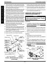
22NF Battery
Hex Nut
FIGURE 5 - CONNECTING BATTERY
CABLES - BATTERY CLAMP METHOD
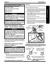
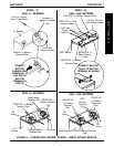
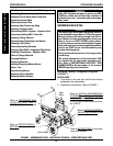
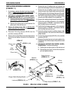
CAUTION
When connecting the battery cable/ring
terminal(s) to the battery(ies) clamp(s), the
battery cable(s) MUSt be connected in the
position shown in DETAIL “A”, otherwise
damage may occur to the battery cable
and/or battery clamp covers.
3. Connect battery cable(s) to battery(ies) terminal(s)/
post(s) as follows (DETAIL “A”):
A. NEGATIVE (-) BLACK battery cable/ring terminal
between the mounting plate and battery clamp of
NEGATIVE (-) battery terminal/post.
B. POSITIVE (+) RED battery cable/ring terminal be-
tween the mounting plate and battery clamp bat-
tery clamp of POSITIVE (+) battery terminal/post.
4. Secure the battery cable(s)/ring terminal(s) to the bat-
tery clamp(s), BLACK to NEGATIVE (-) and RED to
POSITIVE (+), with exisitng hex screws. Securely
Tighten. (DETAIL “A”)
5. Verify battery cable ring terminal(s) are correctly in-
stalled and securely tightened.
6. Slide battery clamp covers down battery cables and
onto battery terminals. (DETAIL “B”)
7. Secure each terminal cap in place with a tie-wrap
(Use tie-wraps 11-1/2-inches long). (DETAIL “B”)
NOTE: It will be necessary to trim excess tie-wrap in
order to install the battery box top(s).
8. Install the battery box top(s).
CORRECT ORIENTATION OF THE POSITIVE (+)
BATTERY TERMINAL/POST BATTERY CLAMP
INSTALLING BATTERY CLAMP COVERS
PROCEDURE 7 BATTERIES
B
A
T
T
E
R
I
E
S