


53
REPLACING THE MOTOR/
GEARBOX (FIGURE 1)
WARNING
The following procedure should only be performed
by an Invacare dealer or qualified technician.
1. Remove the battery boxes. Refer to INSTALLING/
REMOVING BATTERY BOX(ES) in PROCEDURE
6 of this manual.
2. Disconnect the right and/or left motor connector from
the controller.
3. Remove the rear wheels from the wheelchair. Refer
to INSTALLING/REPLACING REAR WHEEL AS-
SEMBLIES in PROCEDURE 10 of this manual.
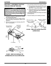
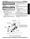
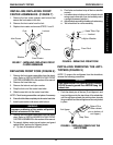
4. Remove the six (6) socket screws that secure the mo-
tor/gearbox and support tube to the wheelchair frame.
5. Reposition the new motor/gearbox on the wheelchair
frame.
CAUTION
The longer socket screws must be positioned in the
mounting holes on the OUTSIDE of the wheelchair
frame and the short socket screws must be in the
mounting holes on the INSIDE of the wheelchair
frame. Otherwise damage to the gearbox casting
can result.
6. Use Loctite 242 and securely tighten the motor/gear-
box to the wheelchair frame with the six (6) socket
screws. Torque to 60-inch pounds.
7. Reinstall the rear wheels onto the wheelchair. Refer
to INSTALLING/REPLACING REAR WHEEL AS-
SEMBLIES in PROCEDURE 10 of this manual.
8. Reconnect the right and/or left motor connector to
the controller.
9. Repeat procedure for opposite side of the wheelchair,
if necessary.
10. Reinstall the battery boxes. Refer to INSTALLING/
REMOVING BATTERY BOX(ES) in PROCEDURE
6 of this manual.
This Procedure includes the following:
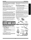
Replacing the Motor/Gearbox
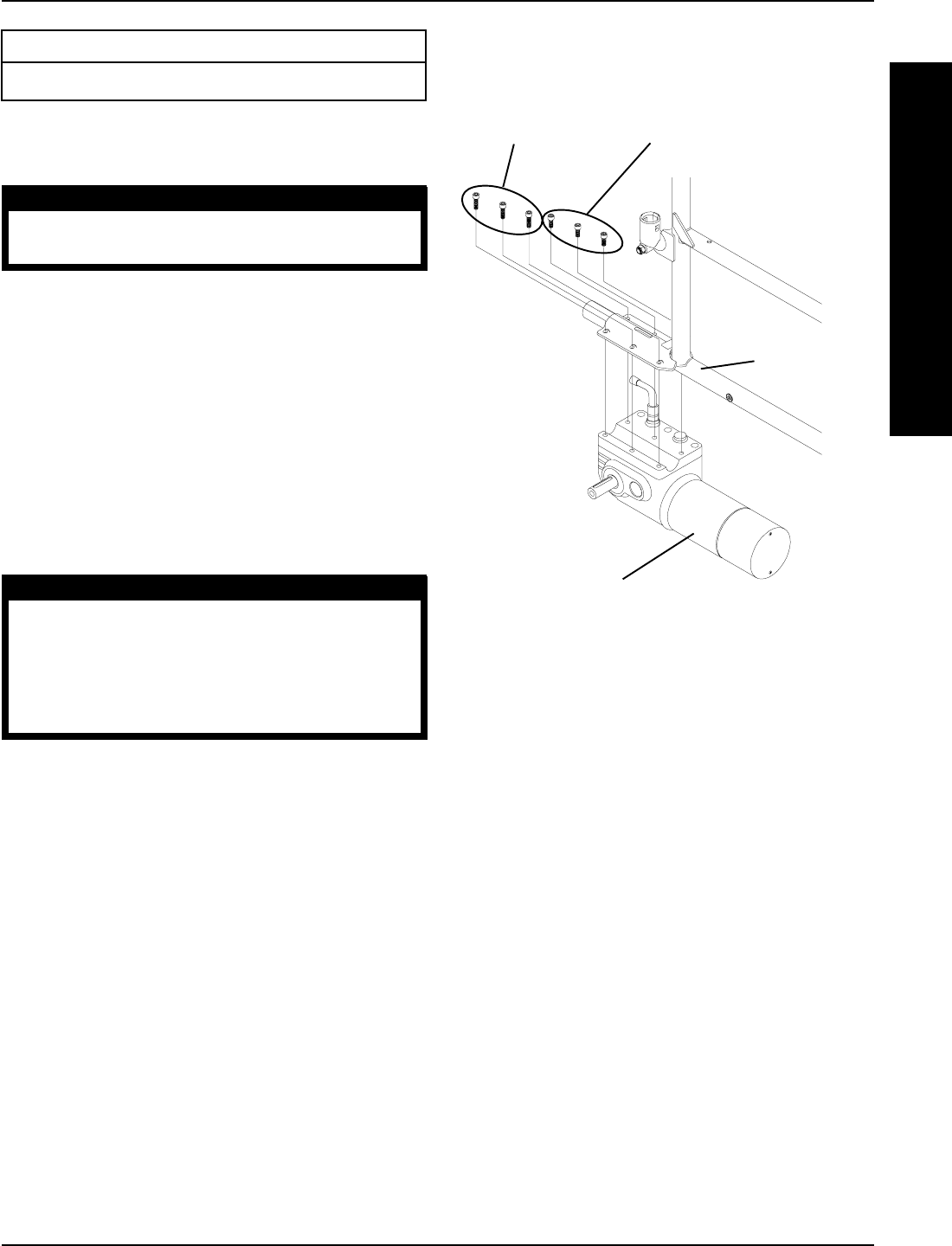
Wheelchair
Frame
FIGURE 1 - REPLACING THE MOTOR/GEARBOX
Long Socket
Screws (Apply
Loctite 242 and
torque to 60-
inch pounds)
Short Socket Screws
(Apply Loctite 242 and
torque to 60-inch pounds)
Motor/Gearbox
PROCEDURE 11MOTOR/GEARBOX
M
O
T
O
R
/
G
E
A
R
B
O
X