


51
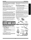
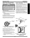
b. Pivot forks and casters to top of their arc simulta-
neously.
c. Let casters drop to bottom of arc (wheels should
swing once to one-side, then immediately rest in
a straight downward position).
d. Adjust locknuts according to freedom of caster swing.
e. Test wheelchair for maneuverability.
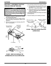
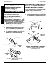
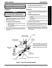
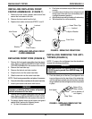
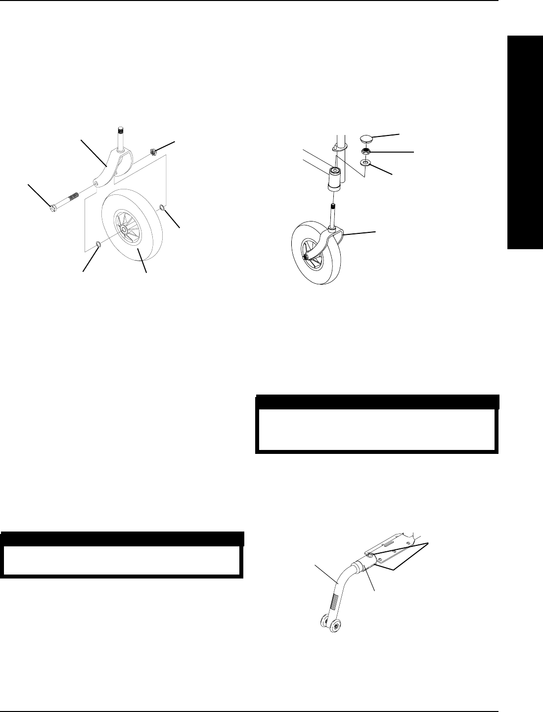
INSTALLING/REPLACING FRONT
CASTER ASSEMBLIES (FIGURE 7)
1. Remove the hex screw, spacers and locknut that
secure the front caster to the fork.
2. Remove the front caster from the fork.
3. Replace front caster and reverse STEPS 1 and 2.
Hex Screw
Locknut
Fork
Washer
Front Caster
Washer
FIGURE 7 - INSTALLING/REPLACING FRONT
CASTER ASSEMBLIES
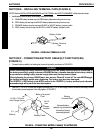
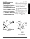
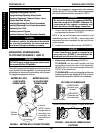
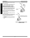
REPLACING FRONT FORK (FIGURE 8)
1. Remove the front caster assemblies from the wheel-
chair. Refer to INSTALLING/REPLACING FRONT
CASTER ASSEMBLIES in this section of the manual.
2. Remove the head tube cap.
3. Remove the locknut and nylon washer.
4. Drop the fork out of the caster head tube.
5. Slide the new fork into the caster head tube.
NOTE: Check bearing assemblies and replace if necessary.
6. Ensure that fork slides completely into the caster head tube.
7. Install nylon washer and secure with locknut.
WARNING
Improper positioning of the washer will prohibit
the free movement of the forks.
8. Remove the front caster assemblies from the wheel-
chair. Refer to INSTALLING/REPLACING FRONT
CASTER ASSEMBLIES in this section of the manual.
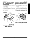
9. To properly tighten caster journal system and guard
against flutter, perform the following check:
a. Tip front of wheelchair off floor.
FIGURE 8 - REPLACING FRONT FORK
Front Fork
Nylon Washer
Locknut
Head Tube Cap
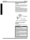
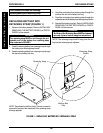
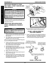
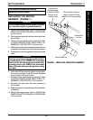
INSTALLING/REMOVING THE ANTI-
TIPPERS (FIGURE 9)
NOTE: To remove the anti-tippers from the wheelchair,
reverse the following procedures.
WARNING
Anti-tippers MUST be attached and pointing
DOWN towards ground/floor BEFORE using the
wheelchair.
1. Push the detent pins of the two (2) anti-tippers in and
insert anti-tippers into the step tubes of the wheelchair
until the anti-tipper wheels are pointing down towards
the ground/floor and the anti-tippers are securely locked
in place.
FIGURE 9 - INSTALLING/REMOVING THE
ANTI-TIPPERS
Anti-tipper
Step Tube
Detent Pins
(Other detent
pin on bottom of
anti-tipper.)
WHEELS/ANTI-TIPPER PROCEDURE 10
W
H
E
E
L
S
/
A
N
T
I
-
T
I
P
P
E
R