


49
USING/INSTALLING/ADJUSTING
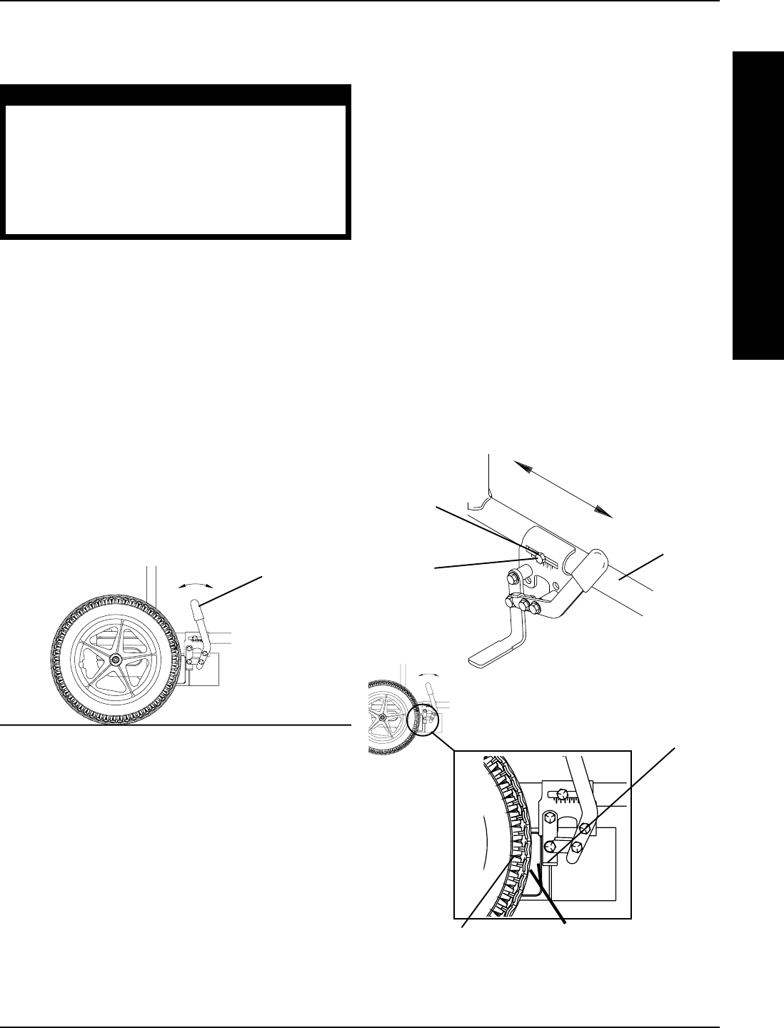
WHEEL LOCKS* (FIGURES 3 AND 4)
WARNING
*Wheel locks are an OPTION on this wheelchair,
(you may order with or without wheel locks). Trans-
fer to and from the wheelchair in the presence of
a qualified healthcare professional to determine
individual safety limits. Invacare strongly recom-
mends ordering the wheel locks as an additional
safeguard for the Action wheelchair user.
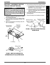
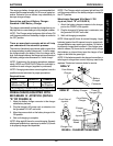
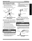
Using the Wheel Locks
The wheelchair is optionally equipped with a pair of inde-
pendently operated wheel locks located just in front of the
rear wheels.
1. To engage the wheel locks, grip the handle and push
forward to the lock position.
2. To release, reverse the STEP 1.
IMPORTANT NOTE: DO NOT use the wheel locks when
the wheelchair power is ON and the clutches are engaged.
NOTE: Use the wheel locks whenever the clutches are
disengaged and the wheelchair is being pushed.
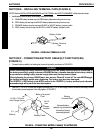
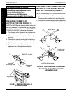
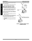
Installing/Adjusting the Wheel Locks
NOTE: Before adjusting or replacing the wheel lock as-
semblies, ensure that the tires are inflated to the recom-
mended psi on the side wall of tire.
1. Position the wheel lock on the wheelchair frame.
2. Loosely install the hex screw and washer that secures
the wheel lock to the wheelchair frame.
3. Make sure the wheel lock is disengaged from the
rear wheel.
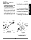
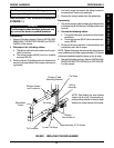
FIGURE 4 - INSTALLING/ADJUSTING
THE WHEEL LOCKS
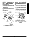
4. Measure the distance between the WHEEL LOCK
SHOE and the REAR WHEEL.
5. Slide the wheel lock along the wheelchair until the
measurement is between 5/32 and 5/16-inches.
6. Tighten the wheel lock to the wheelchair frame with
the hex screw and washer.
7. Repeat this procedure for the opposite wheel lock.
8. Disengage the clutches. Refer to ENGAGING/DIS-
ENGAGING CLUTCHES in this section of the manual.
9. Engage the wheel locks and push against the wheel-
chair to determine if the wheel locks engage the rear
wheels enough to hold the wheelchair.
10. Repeat STEPS 3-8 until the wheel locks engage the
rear wheels enough to hold the wheelchair.
11. Engage the clutches. Refer to ENGAGING/DISEN-
GAGING CLUTCHES in this section of the manual.
5/32 to 5/16-inch
Wheel Lock
Shoe
Rear Wheel
Hex
Screw
Wheelchair
Frame
Washer
FIGURE 3 - USING THE WHEEL LOCKS
Wheel Lock
Handle
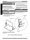
W
H
E
E
L
S
/
A
N
T
I
-
T
I
P
P
E
R
WHEELS/ANTI-TIPPER PROCEDURE 10