


44
E
L
E
C
T
R
O
N
I
C
S
PROCEDURE 7 ELECTRONICS
This Procedure includes the following:
Preparing the MKIV-RII Joystick for Use
Disconnecting/Connecting the MKIV-RII-LP
Controller Motor and Battery Leads
Repositioning the MKIV-RII Joystick
Removing/Installing the MKIV-RII-LP Controller
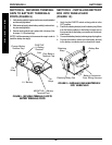
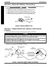
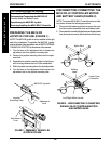
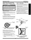
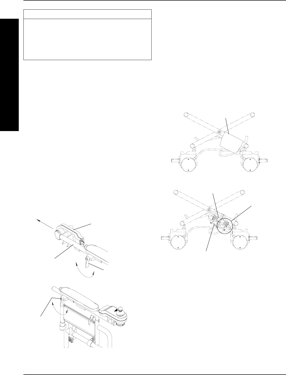
PREPARING THE MKIV-RII
JOYSTICK FOR USE (FIGURE 1)
NOTE: The MKIV-RII joystick is factory installed on the right
side of the wheelchair. To reposition the MKIV-RII joystick
onto the left side of the wheelchair, refer to REPOSITIONING
THE MKIV-RII JOYSTICK in this section of the manual.
1. Turn the lever on the adjustment lock to release the
adjustment lock from joystick mounting tube.
2. Remove the joystick mounting tube from the adjust-
ment lock.
3. Reposition the joystick mounting tube so that the joy-
stick is facing towards the front of the wheelchair.
4. Slide the joystick mounting tube to the desired position.
5. Turn the lever on the adjustment lock to secure the
adjustment lock to the joystick mounting tube.
Joystick
Mounting Tube
Adjustment
Lock
MKIV-RII Joystick
FIGURE 1 - PREPARING THE MKIV-RII
JOYSTICK FOR USE
Adjustment
Lock
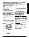
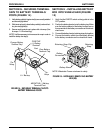
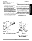
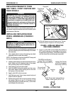
DISCONNECTING/CONNECTING THE
MKIV-RII-LP CONTROLLER MOTOR
AND BATTERY LEADS (FIGURE 2)
NOTE: To connect MKIV-RII-LP controller motor and bat-
tery leads, reverse the following procedure.
1. Disconnect the fastening straps that secure the nylon
boot around the connected motor and battery leads.
2. Disconnect the controller left/right motor and battery leads
from the leads secured to the wheelchair with tie wrap.
FIGURE 2 - DISCONNECTING/CONNECTING
THE MKIV-RII-LP CONTROLLER MOTOR
AND BATTERY LEADS
Battery
Lead
Left/Right Motor Leads
Leads From
Controller
Nylon Boot