


47
This Procedure includes the following:
Replacing the Wiring Harness
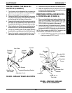
4. Cut the tie wraps that secure the wiring harness to
the wheelchair frame and crossbrace.
5. Remove the wiring harness from the wheelchair.
Reassembly
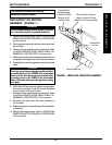
1. Secure the charger cable to existing mounting bracket
on the seat frame with the two (2) phillips screws and
locknuts.
2. Connect the following cables:
a. The right and left motor connectors to the controller
connectors.
b. The wiring harness (BLUE) to the controller con-
nector (BLUE).
3. Re-secure the wiring harness to the wheelchair and
crossbraces with new tie wraps.
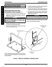
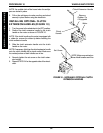
NOTE: Tighten the tie wrap that secures the wiring harness
to the crossbrace until there is approximately 5-1/2-inches
of tie wrap threaded through the clamp on the tie wrap.
4. Reinstall the battery box(es). Refer to INSTALLING/
REMOVING BATTERY BOX(ES) in PROCEDURE
6 of this manual.
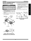
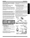
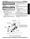
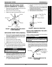
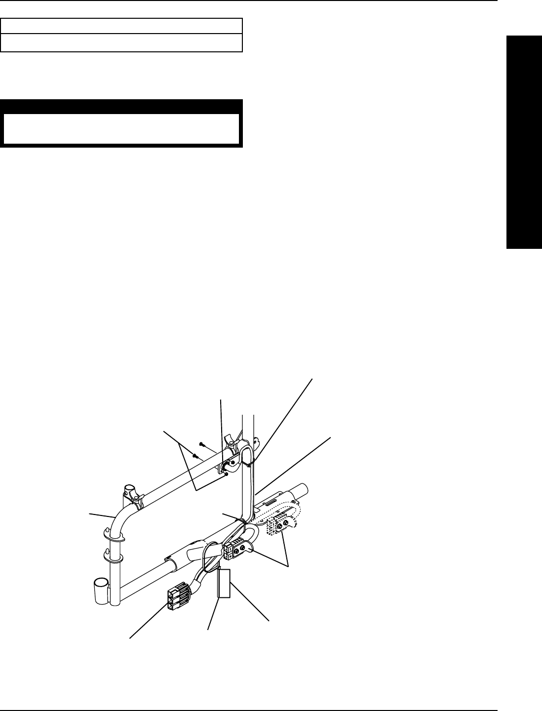
REPLACING THE WIRING HARNESS
(FIGURE 1)
WARNING
The following procedure should be performed only
by an Invacare dealer or qualified technician.
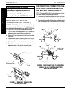
Disassembly
1. Remove the battery box(es). Refer to INSTALLING/
REMOVING THE BATTERY BOX(ES) in PROCE-
DURE 6 of this manual.
2. Disconnect the following cables:
a. The right and left motor connectors from the con-
troller connectors.
b. The wiring harness (BLUE) from the controller
connector (BLUE).
3. Remove the two (2) phillips screws and locknuts that
secure the charger cable to the charger cable mount-
ing bracket.
FIGURE 1 - REPLACING THE WIRE HARNESS
Wiring
Harness
Phillips Screws
and Locknuts
Charger Cable
Mounting Bracket
To Controller
Battery
Connection(s)
Wheelchair
Frame
Tie Wrap
Tie Wrap
NOTE: Dual battery box wire harness
shown only for clarity. Procedure for re-
placing wiring harness for dual or single
battery box wiring harness is the same.
Loose Tie Wrap
Approximately 5-1/2-inches
W
I
R
I
N
G
H
A
R
N
E
S
S
WIRING HARNESS PROCEDURE 9