


50
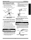
REPLACING PNEUMATIC TIRES
AND TUBES - FRONT CASTERS AND
REAR WHEELS
WARNING
DO NOT use your power wheelchair unless it has
the proper tire pressure (p.s.i.). DO NOT overinflate
the tires. Failure to follow these suggestions may
cause the tire to explode and cause bodily harm.
If tires are pneumatic, replacement of tire or tube
MUST be performed by an Invacare dealer or
qualified technician.
NOTE: If front casters or rear wheels are pneumatic, un-
der-inflation causes excessive wear which results in poor
performance of the tires.
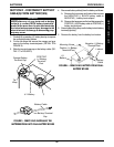
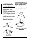
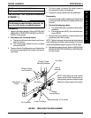
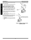
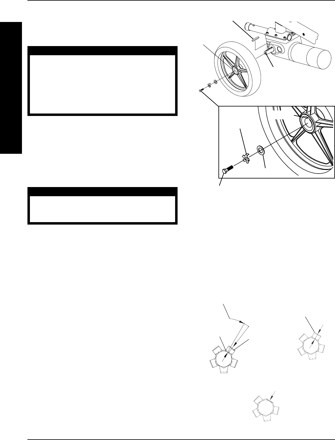
INSTALLING/REPLACING REAR
WHEEL ASSEMBLIES (FIGURES 5
AND 6)
WARNING
NEVER use a locking tab washer more than once.
ALWAYS use a NEW locking tab washer when in-
stalling the rear wheels.
1. Remove the hex screw, lockwasher and washer that
secure the existing rear wheel assembly to the wheel
hub assembly.
2. Use a wheel puller to remove the existing rear wheel
assembly from the motor drive shaft.
NOTE: The keystock in the wheel hub MUST lineup with
the cutout in the gearbox drive shaft.
3. Install the new/existing rear wheel onto the motor drive
shaft. Make sure the chamfered side of the wheel
hub is pointing away from the wheelchair.
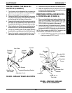
4. Install washer onto motor drive shaft.
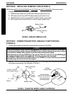
5. Install the NEW locking tab washer onto the motor
drive shaft. Make sure the locking tab is in line with
the keyway of the rear wheel.
6. Apply Loctite 242 to the hex screw.
7. Install the hex screw. Use a torque wrench only and
torque to 90-inch pounds.
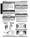
8. Examine the head of the hex screw and the locking
tab washer. Make sure one (1) of the tabs on the
locking tab washer is parallel with one (1) of the flats
on the head of the hex screw.
Motor
Driveshaft
Washer
Locking Tab
Washer
Keyway
Keystock
Chamfered
Side of
Wheel Hub
Hex Screw (Apply Loctite 242 and use a Torque
Wrench only to Torque to 90-inch pounds)
FIGURE 5 - INSTALLING/REPLACING
REAR WHEEL ASSEMBLIES
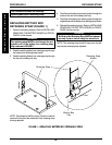
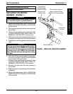
Flat on Head
of Hex Screw
Locking
Tab
9. If one (1) of the tabs on the locking tab washer is
NOT parallel with one (1) of the flats on the head of
the hex screw (FIGURE 6), TIGHTEN the hex screw
until the closest flat and locking tab are parallel.
TIGHTEN Hex Screw if
Locking Tab is not Parallel
with Flat on Head
(STEP 9)
Locking Tab Parallel
with Flat on Head of
Hex Screw
(STEP 9)
Bend Tab up tight against Flat on
Head of Hex Screw
(STEP 10)
FIGURE 6 - LOCKING TABS
W
H
E
E
L
S
/
A
N
T
I
-
T
I
P
P
E
R
WHEELS/ANTI-TIPPERPROCEDURE 10