


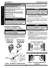
48
This Procedure includes the following:
Engaging/Disengaging Clutches
Using/Installing/Adjusting Wheel Locks
Replacing Pneumatic Tires and Tubes - Front
Casters and Rear Wheels
Installing/Replacing Rear Wheel Assemblies
Installing/Replacing Front Caster Assemblies
Replacing Front Fork
Installing the Anti-Tippers
Installing Optional Clutch Extension Handles
CAUTION
As with any vehicle, the wheels and tires should
be checked periodically for cracks and wear
and should be replaced when necessary.
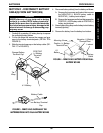
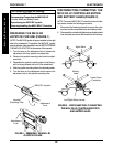
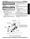
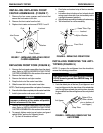
BATTERY BOX FOR
14-INCH WIDE
WHEELCHAIRS
BATTERY BOX FOR
16-20-INCH WIDE
WHEELCHAIRS
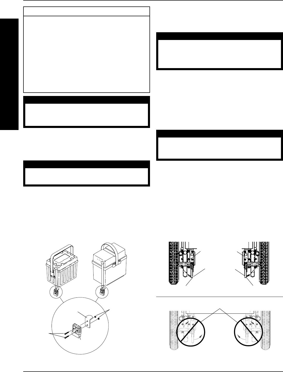
Tab
Battery Box
Connector
Phillips
Screws
Locknuts
NOTE: Confirm
that the tabs on
the battery box
connectors are
assembled as
shown.
FIGURE 1 - BATTERY BOX CONNECTOR TABS
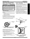
ENGAGING/DISENGAGING
CLUTCHES (FIGURES 1 AND 2)
WARNING
DO NOT engage or disengage the clutches until
the power is in the OFF position.
The clutch engagement/disengagement allows freewheel-
ing or joystick controlled operation. Freewheeling allows
an attendant to maneuver the wheelchair without power.
To engage/disengage the clutches:
NOTE: If the wheelchair is equipped with clutch extension
handles, refer to STEP 1 below. If the wheelchair is not equipped
with clutch extension handles, proceed to STEP 2.
WARNING
The tabs on the battery box connectors MUST be
assembled as shown in FIGURE 2. Otherwise the
connectors will not engage completely and
clutch handles could disengage connectors.
1. Confirm that the tabs on the battery box connectors
are assembled as shown in FIGURE 1.
NOTE: If the tab on the battery box connectors is not
assembled as shown in FIGURE 1, remove the phillips
screws and locknuts to assemble the tab onto the con-
nector correctly.
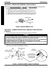
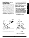
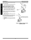
2. Locate the clutch handles on motors (FIGURE 2).
CAUTION
If clutch handles are forced to engage in the
wrong direction (FIGURE 2), the motors will be
damaged and will need to be replaced.
3. Perform one of the following (FIGURE 2):
TO ENGAGE: turn the clutch handles until they
are pointing towards the rear of the wheelchair.
NEVER try to turn the clutch handles towards the
FRONT of the wheelchair.
TO DISENGAGE: turn the clutch handles until they are
pointing towards the rear wheels. NEVER try to turn the
clutch handles towards the INSIDE of the wheelchair.
Clutch Handle
FIGURE 2 - ENGAGING/DISENGAGING
CLUTCHES
NEVER
Force clutch handles in these directions
ENGAGED
(Towards rear
of wheelchair)
Clutch Handle
DISENGAGED
(Towards rear
wheels)
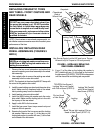
TOP VIEW OF WHEELCHAIR
W
H
E
E
L
S
/
A
N
T
I
-
T
I
P
P
E
R
WHEELS/ANTI-TIPPERPROCEDURE 10