


Solara™ 64 Part No. 1080556 Rev. I
CONTRACTURE FOOTPLATE OPTION
PROCEDURE 11
This Procedure Includes the Following:
Installing The Contracture Footplate Assembly
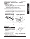
Contracture Assembly Angle Adjustment
Using The Optional Quick-Release Pin
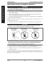
Angle Adjustment of the Contracture Footplate
Contracture Footplate Depth Adjustment
Contracture Footplate Height Adjustment
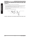
Replacing The Contracture Footplate heel Loop
INSTALLING THE CONTRACTURE FOOTPLATE
ASSEMBLY
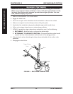
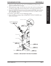
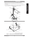
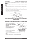
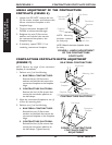
INSTALLING THE CROSSMEMBER ASSEMBLY (FIGURE 1)
NOTE: Invacare recommends that two (2) people perform this procedure.
NOTE: Take note of position and orientation of the mounting hardware for reassembly.
1. If necessary, remove the seating system from the wheelchair. Refer to the seating systems
Owner’s Manual supplied with the wheelchair.
2. Remove the seat pan. Refer to
REMOVING/INSTALLING THE SEAT PAN in the Service
Manual, part number 1085787.
3. Remove the back canes. Refer to
REMOVING/INSTALLING THE BACK CANES in the
Service Manual, part number 1085787.
4. Remove the allen screw, spacer and locknut that secure the link bracket to the lower seat
frame as shown in DETAIL “A” of FIGURE 1.
5. Remove the shoulder screw and locknut securing the rear of the seat frame to the bearing
housing as shown in DETAIL “A” of FIGURE 1.
6. Repeat STEPS 4-5 for opposite side of seat frame.
7. Lift up to remove the seat frame from the base frame.
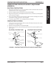
NOTE: When reassembling the seat frame, the front crossbrace will be replaced with the crossmember assem-
bly (insert tube and outer tube) provided in this kit and will be secured with the EXISTING mounting screws.
NOTE: Right and left sides of the seat frame are determined by sitting in the wheelchair.
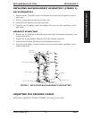
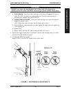
8. On the left hand side of the seat frame, remove the two (2) EXISTING mounting screws
and locknuts that secure the front and rear crossmember to the brace supports of the seat
frame as shown in DETAIL “B” of FIGURE 1.
9. Pull the left hand side of the seat frame away from the front and rear crossmembers.
10. Remove the EXISTING mounting screw, and locknut that secures the other end of the
front crossmember to the front right hand side brace support of the seat frame as shown
in DETAIL “B” of FIGURE 1.
11. Remove the front crossmember from the brace support and discard.
12. Insert one end of the insert tube into the front right hand side brace support.
13. Align mounting holes in the end of the insert tube with the brace support and secure with
the EXISTING mounting screw and locknut.
CONTRACTURE
FOOTPLATE OPTION
CONTRACTURE FOOTPLATE
OPTION