


Solara™ 52 Part No. 1080556 Rev. I
WHEEL LOCKS/ANTI-TIPPERSPROCEDURE 9
Socket Screws
This Procedure Includes the Following:
Wheel Lock Adjustment
Using the Wheel Locks
Installing/Adjusting Anti-Tippers
WARNING
After ANY adjustments, repair or service and BEFORE use, make sure all attach-
ing hardware is tightened securely - otherwise injury or damage may result.
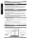
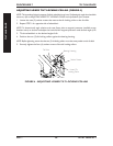
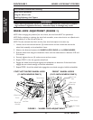
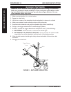
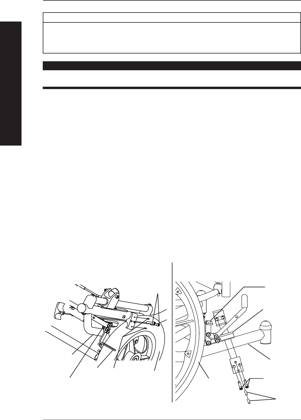
WHEEL LOCK ADJUSTMENT (FIGURE 1)
NOTE: When changing the position of the rear wheels, the wheel locks MUST be repositioned.
NOTE: Before adjusting or replacing the wheel lock assemblies, ensure that the tires are inflated to the
recommended p.s.i on the side wall of the tire.
NOTE: The foot activated wheel locks and the front wheel locks adjust in the same way.
1. Loosen, but do not remove the two (2) socket screws and set screws that secure the
wheel lock assembly to the wheelchair frame.
2. Measure the distance between the WHEEL LOCK SHOE and the REAR WHEEL.
3. Slide the wheel lock along the wheelchair frame until the measurement is between 5/32 and
5/16-inches.
4. Securely tighten the two (2) socket screws and set screws.
5. Repeat STEPS 1-4 for the opposite wheel lock.
6. Engage the wheel locks and push against the wheelchair to determine if the wheel locks
engage the rear wheels enough to hold the wheelchair.
7. Repeat STEPS 1-6 until the wheel locks engage the rear wheels enough to hold the wheelchair.
Wheel Lock
Assembly
Wheelchair
Frame
Socket Screws
FOOT ACTIVATED WHEEL LOCK
(12-INCH WHEELS ONLY)
Wheel
Lock Shoe
Wheelchair Frame
Rear
Wheel
Set Screws
FRONT WHEEL LOCKS
(20-22-INCH WHEELS ONLY)
Wheel Lock
Shoe
FIGURE 1 - WHEEL LOCK ADJUSTMENT
Wheel Lock
Assembly
Set Screws
Rear
Wheel
WHEEL LOCKS/
ANTI-TIPPERS
WHEEL LOCKS/ANTI-TIPPERS