


Part No. 1080556 Rev. I 23 Solara™
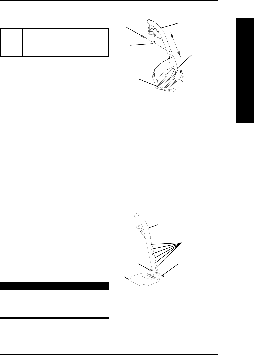
ADJUSTING SWINGAWAY FOOTREST HEIGHT
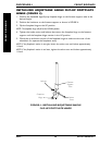
HEIGHT ADJUSTMENT RANGES:
60° 13-17-inches
70° 13-17-inches
90° 5-8-inches
90° 5-11-inches (with 3-inch extension)
NOTE: If using ANY type of extension with the
ADJUSTABLE FLIP-UP FOOTPLATE, refer to
ADJUSTABLE ANGLE FLIP-UP FOOTPLATE PER-
PENDICULAR AND/OR INVERSION/EVERSION
ADJUSTMENT in this procedure of the manual.
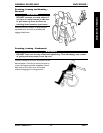
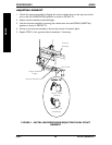
60°, 70° and 70° Taper (FIGURE 2)
1. Remove the footrest from the wheelchair.
Refer to INSTALLING/REMOVING
SWINGAWAY FOOTREST in this procedure of the manual.
2. Remove the hex screw and coved spacer and slide the footrest up or down on its
mounting tube until the desired footrest height is achieved.
3. Reassemble the hex screw and coved spacer through the footrest upper support and
mounting tube as shown in FIGURE 2.
4. Securely tighten the hex screw and coved spacer.
5. Install the footrest assembly onto the wheelchair. Refer to
INSTALLING/REMOVING
SWINGAWAY FOOTREST in this procedure of the manual.
6. Repeat STEPS 1-5 for the opposite side of the wheelchair, if necessary.
FRONT RIGGINGS
Hex Screw
Coved
Spacer
FIGURE 2 - ADJUSTING
SWINGAWAY FOOTREST
HEIGHT - 60°, 70° AND 70° TAPER
Footrest Upper
Support
Mounting
Tube
Footrest
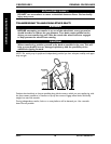
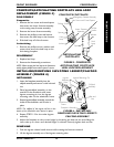
1. Remove any accessories that are attached
to the footrests.
2. Remove the socket bolt, coved washer
and locknut that secure the footplate to
the footrest support.
3. Reposition the footplate to the desired
height.
4. Reinstall the socket bolt through the
mounting holes of the footplate and
footrest support.
WARNING
DO NOT overtighten socket bolt
and locknut. Footrest MUST be able
to rotate upward from the horizon-
tal to the vertical position.
5. Secure the footplate to the footrest
support with the coved washer and
locknut.
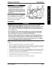
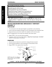
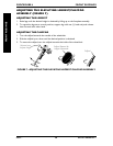
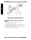
70° MFX AND 90° FOOTRESTS
(FIGURE 3)
FIGURE 3 - INSTALLING/REMOVING/
ADJUSTING THE FOOTREST(S) -
70° MFX AND 90° FOOTRESTS
Height
Adjustment
Holes
Socket Bolt
Locknut
Footrest Support
Footplate
PROCEDURE 4FRONT RIGGINGS
FRONT RIGGINGS