


Reference Manual
00809-0200-4101, Rev AA
July 2008
Rosemount 2051
A-12
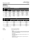
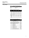
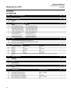
ORDERING
INFORMATION
Model Transmitter Type (Select One) CD CG
2051C Pressure Transmitter • •
Model Measurement Type CD CG
D Differential • —
G Gage — •
Code Pressure Ranges (Range/Min. Span) CD CG
2051CD 2051CG
1 –25 to 25 inH
2
O/0.5 inH
2
O
(–62,2 to 62,2 mbar/1,2 mbar)
–25 to 25 inH
2
O/0.5 inH
2
O
(–62,1 to 62,2 mbar/1,2 mbar)
• •
2 –250 to 250 inH
2
O/2.5 inH
2
O
(–623 to 623 mbar/6,2 mbar)
–250 to 250 inH
2
O/2.5 inH
2
O
(–623 to 623 mbar/6,2 mbar)
• •
3 –1000 to 1000 inH
2
O/10 inH
2
O
(–2,5 to 2,5 bar/25 mbar)
–393 to 1000 inH
2
O/10 inH
2
O
(–0,98 to 2,5 bar/25 mbar)
• •
4 –300 to 300 psi/3 psi
(–20,7 to 20,7 bar/0,2 bar)
–14.2 to 300 psi/3 psi
(–0,98 to 20,7 bar/0,2 bar)
• •
5 –2000 to 2000 psi/20 psi
(–137,9 to137,9 bar/1,4 bar)
–14.2 to 2000 psig/20 psi
(–0,98 to 137,9 bar/1,4 bar)
• •
Code Output CD CG
A 4–20 mA with Digital Signal Based on HART Protocol • •
M Low-Power, 1–5 V dc with Digital Signal Based on HART Protocol • •
F FOUNDATION fieldbus Protocol
• •
Code Materials of Construction CD CG
Process Flange Type Flange Material Drain/Vent
2 Coplanar SST SST • •
3
(1)
Coplanar Cast C-276 Alloy C-276 • •
5 Coplanar Plated CS SST • •
7
(1)
Coplanar SST Alloy C-276 • •
8
(1)
Coplanar Plated CS Alloy C-276 • •
0 Alternate Process Connection (Requires selecting Flange, Manifold, or Primary Element option code, see page
A-13)
• •
Code Isolating Diaphragm CD CG
2
(1)
316L SST ••
3
(1)
Alloy C-276 • •
Code
O-ring
A Glass-filled PTFE ••
B Graphite-filled PTFE • •
Code Fill Fluid CD CG
1 Silicone ••
2 Inert fill (Halocarbon) • •
Code Housing Material Conduit Entry Size CD CG
A Polyurethane-covered Aluminum ½–14 NPT • •
B Polyurethane-covered Aluminum M20 × 1.5 (CM20) • •
D Polyurethane-covered Aluminum G½ ••
J SST (consult factory for availability) ½–14 NPT • •
K SST (consult factory for availability) M20 × 1.5 (CM20) • •
M SST (consult factory for availability) G½ • •