


Reference Manual
00809-0200-4101, Rev AA
July 2008
Rosemount 2051
5-10
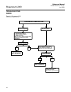
Remove the
Electronics Board
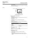
The transmitter electronics board is located in the compartment opposite the
terminal side. To remove the electronics board perform the following
procedure:
1. Remove the housing cover opposite the field terminal side.
2. If you are disassembling a transmitter with a LCD display, loosen the two
captive screws that are visible on the right and left side of the meter
display.
3. Loosen the two captive screws that anchor the board to the housing. The
electronics board is electrostatically sensitive; observe handling
precautions for static-sensitive components. Use caution when removing
the LCD as there is an electronic pin connector that interfaces between
the LCD and electronics board. The two screws anchor the LCD display
to the electronics board and the electronics board to the housing.
4. Using the two captive screws, slowly pull the electronics board out of the
housing. The sensor module ribbon cable holds the electronics board to
the housing. Disengage the ribbon cable by pushing the connector
release.
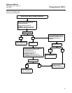
Remove the Sensor
Module from the
Electronics Housing
1. Remove the electronics board. Refer to “Remove the Electronics Board”
on page 5-10.
IMPORTANT
To prevent damage to the sensor module ribbon cable, disconnect it from the
electronics board before you remove the sensor module from the electrical
housing.
2. Carefully tuck the cable connector completely inside of the internal black
cap.
NOTE
Do not remove the housing until after you tuck the cable connector completely
inside of the internal black cap. The black cap protects the ribbon cable from
damage that can occur when you rotate the housing.
3. Loosen the housing rotation set screw with a
5
/64-inch hex wrench, and
loosen one full turn.
4. Unscrew the module from the housing, making sure the black cap and
sensor cable do not catch on the housing.