


Reference Manual
00809-0200-4101, Rev AA
July 2008
A-5
Rosemount 2051
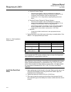
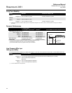
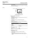
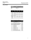
Load Limitations
Maximum loop resistance is determined by the voltage level of the external
power supply, as described by:
Table A-1.
F
OUNDATION
™
fieldbus (Output Code F)
Power Supply
External power supply required; transmitters operate on 9.0 to 32.0 V dc
transmitter terminal voltage.
Current Draw
17.5 mA for all configurations (including LCD display option)
Turn-On Time
Performance within specifications less than 20.0 sections after power is
applied to the transmitter.
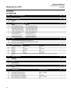
FOUNDATION fieldbus Function Block Execution Times
F
OUNDATION fieldbus Parameters
Standard Function Blocks
Resource Block
• Contains hardware, electronics, and diagnostic information.
Transducer Block
• Contains actual sensor measurement data including the sensor
diagnostics and the ability to trim the pressure sensor or recall factory
defaults.
Maximum Loop Resistance = 43.5 * (Power Supply Voltage – 10.5)
The HART communicator requires a minimum
loop resistance of 250Ω for communication.
Block Execution Time
Resource -
Transducer -
LCD Block -
Analog Input 1, 2 30 milliseconds
PID 45 milliseconds
Schedule Entries 7 (max.)
Links 20 (max.)
Virtual Communications Relationships
(VCR)
12 (max.)
Voltage (V dc)
Load (Ohms)
Operating
Region
1387
1000
500
0
10.5 20 30
42.4