


Reference Manual
00809-0200-4101, Rev AA
July 2008
2-23
Rosemount 2051
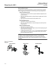
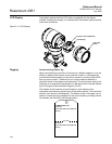
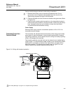
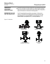
Perform the following procedure to make wiring connections:
1. Remove the housing cover on terminal compartment side. Do not
remove the cover in explosive atmospheres when the circuit is live.
Signal wiring supplies all power to the transmitter.
2. Connect the leads to the two F
OUNDATION fieldbus wiring terminals. Refer
to Figure 2-14.
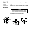
3. Plug and seal unused conduit connection on the transmitter housing to
avoid moisture accumulation in the terminal side. Install wiring with a drip
loop. Arrange the drip loop so the bottom is lower than the conduit
connections and the transmitter housing.
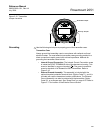
Power Supply
External power supply required; transmitters operate on 9.0 to 32.0 V dc
transmitter terminal voltage.
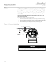
Transient Protection
Terminal Block
The transmitter will withstand electrical transients of the energy level usually
encountered in static discharges or induced switching transients. However,
high-energy transients, such as those induced in wiring from nearby lightning
strikes, can damage the transmitter.
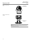
The transient protection terminal block can be ordered as an installed option
(Option Code T1 in the transmitter model number) or as a spare part to retrofit
existing 2051 transmitters in the field. See “Spare Parts” on page A-38 for
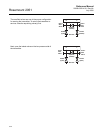
spare part numbers. The lightning bolt symbol shown in Figure 2-14 and
Figure identifies the transient protection terminal block.
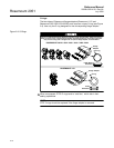
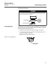
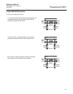
Figure 2-14. Wiring with transient protection
See “Safety Messages” on page 2-1 for complete warning information.
DP
Trim shield and insulate
Insulate
Shield
Connect Shield Back
to the Power Supply
Ground