


Reference Manual
00809-0200-4101, Rev AA
July 2008
Rosemount 2051
5-11
REASSEMBLY
PROCEDURES
1. Inspect all cover and housing (non-process wetted) O-rings and replace
if necessary. Lightly grease with silicone lubricant to ensure a good seal.
2. Carefully tuck the cable connector completely inside the internal black
cap. To do so, turn the black cap and cable counterclockwise one
rotation to tighten the cable.
3. Lower the electronics housing onto the module. Guide the internal black
cap and cable through the housing and into the external black cap.
4. Turn the module clockwise into the housing.
IMPORTANT
Make sure the sensor ribbon cable and internal black cap remain completely
free of the housing as you rotate it. Damage can occur to the cable if the
internal black cap and ribbon cable become hung up and rotate with the
housing.
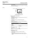
5. Thread the housing completely onto the sensor module. The housing
must be no more than one full turn from flush with the sensor module to
comply with explosion proof requirements.
6. Tighten the housing rotation set screw using a
5
/64-inch hex wrench.
Attach the
Electronics Board
1. Remove the cable connector from its position inside of the internal black
cap and attach it to the electronics board.
2. Using the two captive screws as handles, insert the electronics board
into the housing. Make sure the posts from the electronics housing
properly engage the receptacles on the electronics board. Do not force.
The electronics board should slide gently on the connections.
3. Tighten the captive mounting screws.
4. Replace the electronics housing cover. The transmitter covers must be
engaged metal-to-metal to ensure a proper seal and to meet
Explosion-Proof requirements.
Install the Terminal Block 1. Gently slide the terminal block into place, making sure the two posts from
the electronics housing properly engage the receptacles on the terminal
block.
2. Tighten the captive screws.
3. Replace the electronics housing cover. The transmitter covers must be
fully engaged to meet Explosion-Proof requirements.
Reassemble the 2051C
Process Flange
1. Inspect the sensor module PTFE o-rings. Undamaged o-rings may be
reused. Replace o-rings that show any signs of damage, such as nicks,
cuts, or general wear.
NOTE
If you are replacing the o-rings, be careful not to scratch the o-ring grooves or
the surface of the isolating diaphragm when removing the damaged o-rings.
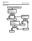
2. Install the process connection. Possible options include:
See “Safety Messages” on page 5-1 for complete warning information.