


Reference Manual
00809-0200-4101, Rev AA
July 2008
4-3
Rosemount 2051
NOTE
As a safety measure, the switch must be reset every time power is interrupted
to the device in order to enable SIMULATE. This prevents a device that is
tested on the bench from getting installed in the process with SIMULATE still
active.
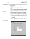
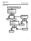
2. To change both the OUT_VALUE and OUT_STATUS of the AI Block, set
the TARGET MODE to AUTO.
3. Set SIMULATE_ENABLE_DISABLE to ‘Active’.
4. Enter the desired SIMULATE_VALUE to change the OUT_VALUE and
SIMULATE_STATUS_QUALITY to change the OUT_STATUS.
• If errors occur when performing the above steps, be sure that the
SIMULATE jumper has been reset after powering up the device.
CALIBRATION
Sensor Calibration,
Upper and Lower Trim
Methods
Sensor Transducer
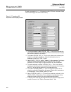
In order to calibrate the transmitter, run the Upper and Lower Trim Methods. If
your system does not support methods, manually configure the Transducer
Block parameters listed below.
1. Set MODE_BLK.TARGET to OOS
2. Set CAL_UNIT to supported engineering units in the Transducer Block
3. Apply physical pressure that corresponds to the lower calibration point
and allow the pressure to stabilize. The pressure must be between the
range limits defined in PRIMRY_VALUE_RANGE.
4. Set values of CAL_POINT_LO to correspond to the pressure applied to
the sensor.
5. Apply pressure, upper cal point.
6. Set CAL_POINT_HI
NOTE
CAL_POINT_HI must be within PRIMARY_VALUE_RANGE and greater than
CAL_POINT_LO + CAL_MIN_SPAN
7. Set SENSOR_CAL_DATE to the current date.
8. Set SENSOR_CAL_WHO to the person responsible for the calibration.
9. Set SENSOR _CAL_LOC to the calibration location.
10. Set SENSOR_CAL_METHOD to User Trim
11. Set MODE_BLK.TARGET to AUTO