


Reference Manual
00809-0200-4101, Rev AA
July 2008
Rosemount 2051
3-8
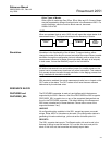
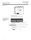
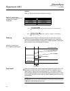
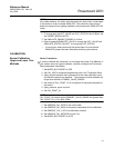
Situation #3
The transmitter in situation #3 is installed below the tank in a position where
the liquid column in the impulse line, with an empty tank, is equivalent to 2.0
psi (see Figure 3-2).
Figure 3-2. Situation #3
Diagram.
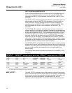
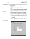
Solution to situation #3
Table 3-4 lists the appropriate configuration settings.
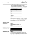
Table 3-4. Analog Input function
block configuration for a
pressure transmitter used in
level measurement
(Situation #3).
In this example, when the PV is 4 psi, OUT will be calculated as follows:
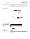
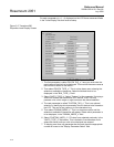
Differential pressure
transmitter to measure flow
Situation #4
The liquid flow in a line is to be measured using the differential pressure
across an orifice plate in the line. Based on the orifice specification sheet, the
differential pressure transmitter was calibrated for 0 to 20 inH
2
0 for a flow of 0
to 800 gal/min.
16 ft
0 ft
2.0 psi measured at
the transmitter
Empty Tank
Parameter Configured Values
L_TYPE Indirect
XD_SCALE 2 to 9 psi
OUT_SCALE 0 to 16 ft
Channel 1 - pressure
OUT = 4 psi – 2 psi * (16 ft. – 0 ft.) + 0 ft. = 4.57 ft.
9 psi – 2 psi