


Reference Manual
00809-0200-4101, Rev AA
July 2008
Rosemount 2051
2-10
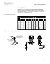
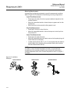
Mount the Transmitter Process Flange Orientation
Mount the process flanges with sufficient clearance for process connections.
For safety reasons, place the drain/vent valves so the process fluid is directed
away from possible human contact when the vents are used. In addition,
consider the accessibility for a testing or calibration input.
NOTE
Most transmitters are calibrated in the horizontal position. Mounting the
transmitter in any other position will shift the zero point to the equivalent
amount of liquid head pressure caused by the varied mounting position. To
reset zero point, refer to “Sensor Trim” on page 4-5.
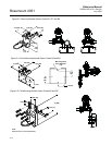
Terminal Side of Electronics Housing
Mount the transmitter so the terminal side is accessible. Clearance of 0.75-in.
(19 mm) is required for cover removal. Use a conduit plug on the unused side
of the conduit opening.
Circuit Side of Electronics Housing
Provide 0.75 in. (19 mm) of clearance for units without an LCD display.
Provide 3 in. (76 mm) of clearance for units installed with LCD.
Cover Installation
Always ensure a proper seal by installing the electronics housing covers so
that metal contacts metal. Use Rosemount o-rings.
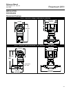
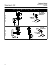
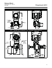
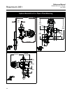
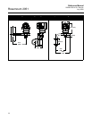
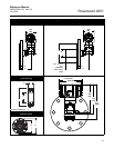
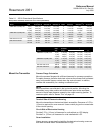
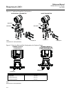
Table 2-1. 2051L Dimensional Specifications
Except where indicated, dimensions are in inches (millimeters).
Class
Pipe
Size
Flange
Thickness A
Bolt Circle
Diameter B
Outside
Diameter C
No. of
Bolts
Bolt Hole
Diameter
Extension
Diameter
(1)
D
O.D. Gasket
Surface E
ASME B16.5 (ANSI) 150 2 (51) 0.69 (18) 4.75 (121) 6.0 (152) 4 0.75 (19) NA 3.6 (92)
3 (76) 0.88 (22) 6.0 (152) 7.5 (191) 4 0.75 (19) 2.58 (66) 5.0 (127)
4 (102) 0.88 (22) 7.5 (191) 9.0 (229) 8 0.75 (19) 3.5 (89) 6.2 (158)
ASME B16.5 (ANSI) 300 2 (51) 0.82 (21) 5.0 (127) 6.5 (165) 8 0.75 (19) NA 3.6 (92)
3 (76) 1.06 (27) 6.62 (168) 8.25 (210) 8 0.88 (22) 2.58 (66) 5.0 (127)
4 (102) 1.19 (30) 7.88 (200) 10.0 (254) 8 0.88 (22) 3.5 (89) 6.2 (158)
DIN 2501 PN 10–40 DN 50 20 mm 125 mm 165 mm 4 18 mm NA 4.0 (102)
DIN 2501 PN 25/40 DN 80 24 mm 160 mm 200 mm 8 18 mm 65 mm 5.4 (138)
DN 100 24 mm 190 mm 235 mm 8 22 mm 89 mm 6.2 (158)
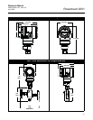
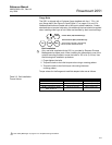
Class
(1)
(1) Tolerances are -0.020 and +0.040 (-0,51 and +1,02)
Pipe
Size
Process
Side F
Lower Housing G
H1/4 NPT 1/2 NPT
ASME B16.5 (ANSI) 150 2 (51) 2.12 (54) 0.97 (25) 1.31 (33) 5.65 (143)
3 (76) 3.6 (91) 0.97 (25) 1.31 (33) 5.65 (143)
4 (102) 3.6 (91) 0.97 (25) 1.31 (33) 5.65 (143)
ASME B16.5 (ANSI) 300 2 (51) 2.12 (54) 0.97 (25) 1.31 (33) 5.65 (143)
3 (76) 3.6 (91) 0.97 (25) 1.31 (33) 5.65 (143)
4 (102) 3.6 (91) 0.97 (25) 1.31 (33) 5.65 (143)
DIN 2501 PN 10–40 DN 50 2.4 (61) 0.97 (25) 1.31 (33) 5.65 (143)
DIN 2501 PN 25/40 DN 80 3.6 (91) 0.97 (25) 1.31 (33) 5.65 (143)
DN 100 3.6 (91) 0.97 (25) 1.31 (33) 5.65 (143)