


Reference Manual
00809-0200-4101, Rev AA
July 2008
Rosemount 2051
2-16
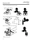
Mounting Requirements
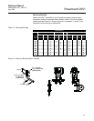
Impulse piping configurations depend on specific measurement conditions.
Refer to Figure 2-8 for examples of the following mounting configurations:
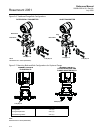
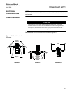
Liquid Flow Measurement
• Place taps to the side of the line to prevent sediment deposits on the
process isolators.
• Mount the transmitter beside or below the taps so gases vent into the
process line.
• Mount drain/vent valve upward to allow gases to vent.
Gas Flow Measurement
• Place taps in the top or side of the line.
• Mount the transmitter beside or above the taps so to drain liquid into
the process line.
Steam Flow Measurement
• Place taps to the side of the line.
• Mount the transmitter below the taps to ensure that impulse piping will
remain filled with condensate.
• In steam service above 250 °F (121 °C), fill impulse lines with water to
prevent steam from contacting the transmitter directly and to ensure
accurate measurement start-up.
NOTE
For steam or other elevated temperature services, it is important that
temperatures at the process connection do not exceed the transmitter’s
process temperature limits. See “Process Temperature Limits” on page A-7
for details.
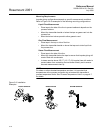
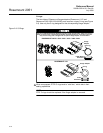
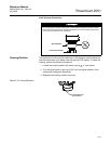
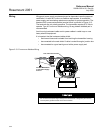
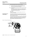
Figure 2-8. Installation
Examples
LIQUID SERVICE GAS SERVICE STEAM SERVICE
F
lo
w
F
lo
w
F
lo
w